Techniques for controlling movement of a set of cables

a technology of moving cables and cables, applied in the field of techniques, can solve the problems of increasing the cost of assembling the final electronic system, tedious and meticulous opening and closing of technicians, and the cost of the metallic cable carrier that is difficult to manufacture, and achieves the effect of reliable and inexpensive process

Inactive Publication Date: 2006-04-04
EMC IP HLDG CO LLC
View PDF5 Cites 28 Cited by
  • Summary
  • Abstract
  • Description
  • Claims
  • Application Information

AI Technical Summary

Benefits of technology

[0012]In one arrangement, the contiguous, unitary body includes homogenous plastic material (e.g., polypropylene) which provides resiliency and flexibility at the set of hinges to enable the support portions to pivot relative to each other within a common plane. In this arrangement, certain support portions preferably have I-beam-shaped cross-sections to provide stiffness to those portions. Accordingly, the arm member is capable of being manufactured in a reliable and inexpensive process such as supplying molten plastic polymer into a mold that defines the particular features of the arm member (e.g., an injection molding process).

Problems solved by technology

Unfortunately, there are deficiencies to the above-described conventional electronic cabinet which uses a metallic cable carrier having metallic beams and metallic hinges.
As a result, the cost to manufacture each individual component and to subsequently assemble the components to form the conventional metallic cable carrier makes the conventional metallic cable carrier somewhat expensive and difficult to manufacture.
Additionally, during installation of the cables onto the conventional metallic cable carrier, the technician must tediously and meticulously open and close individual clips in order to secure the cables to the carrier.
Such a process is time consuming and thus increases the cost of assembling the final electronic system.
Furthermore, since the conventional metallic cable carrier is composed of many parts (e.g., separate metallic beams, hinges, clips etc.), the carrier is susceptible to many potential points of failure.
For example, it is possible for a clip or a hinge to inadvertently detach from a metal beam due to improper assembly or due to an accidental force applied to the carrier at the back of the electronic cabinet.
Such detachment can result in improper operation of the carrier when the chassis slides out of or back into place.
Moreover, complete detachment of a carrier component (e.g., the axle of a hinge) could cause damage to another part of the electronic system (e.g., a metallic part detaching from the carrier could short other electronic circuitry).

Method used


Image

  • Techniques for controlling movement of a set of cables
  • Techniques for controlling movement of a set of cables
  • Techniques for controlling movement of a set of cables

Examples


Embodiment Construction

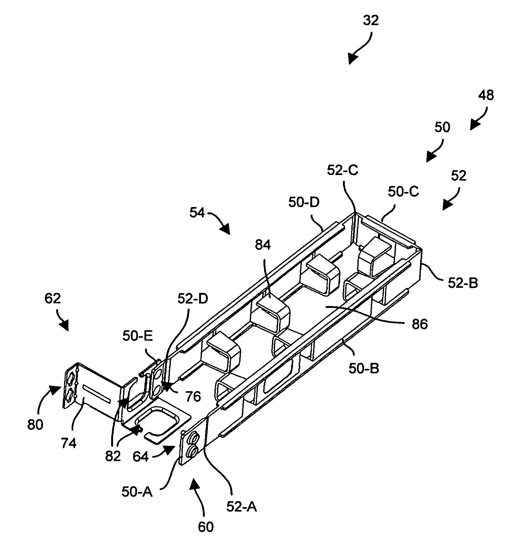
[0020]Embodiments of the invention are directed to techniques for guiding movement of a set of cables (i.e., one or more cables) in an electronic system using an arm member having a set of support portions and a set of hinges which are integrated together to form a contiguous, unitary body (e.g., a solid piece of homogenous plastic material). Utilization of such an arm member within the electronic system provides controlled movement of the set of cables but enables a reduction in manufacturing costs (e.g., less parts and time required for assembly) and an improvement in reliability (e.g., less potential points of failure).

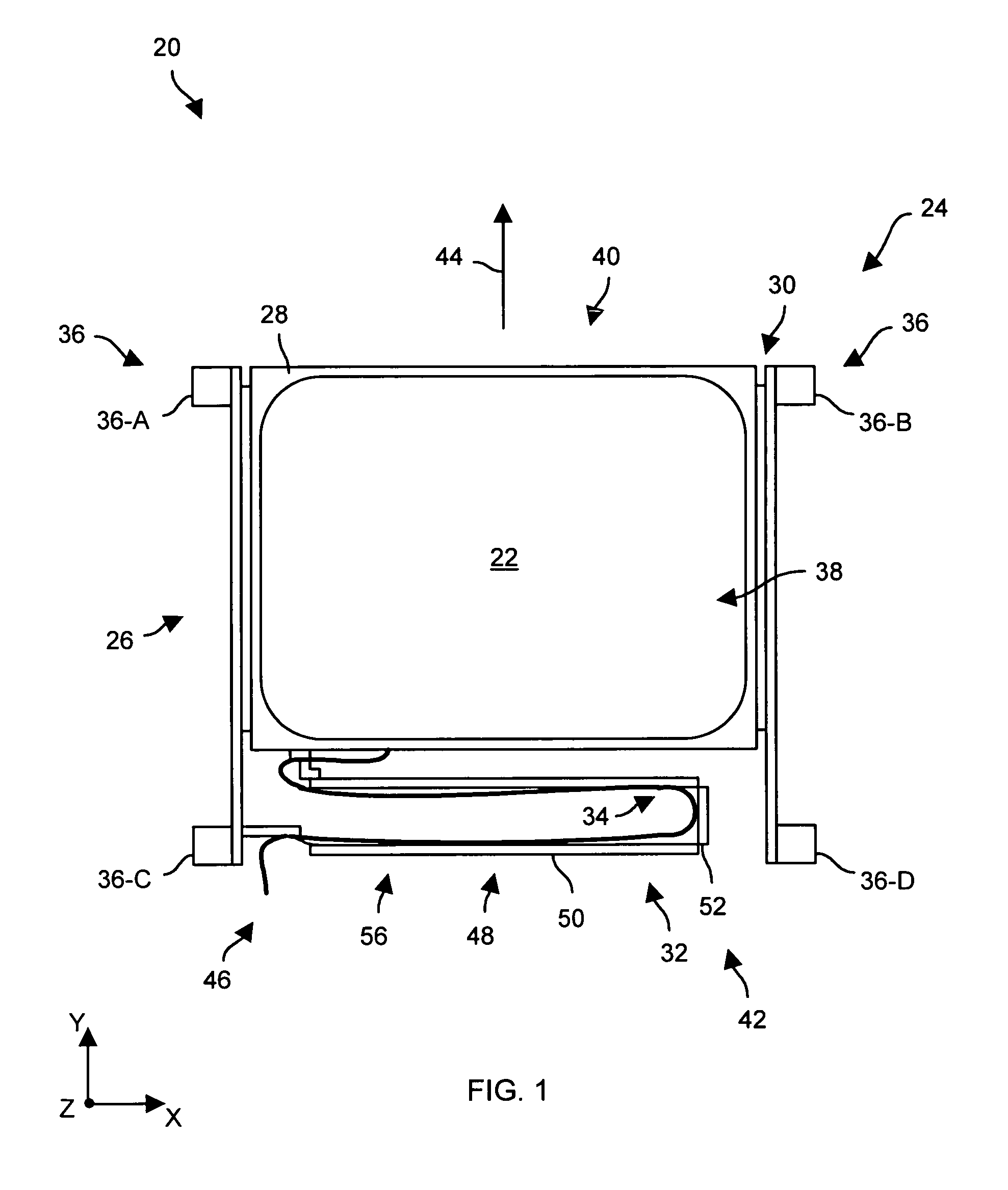
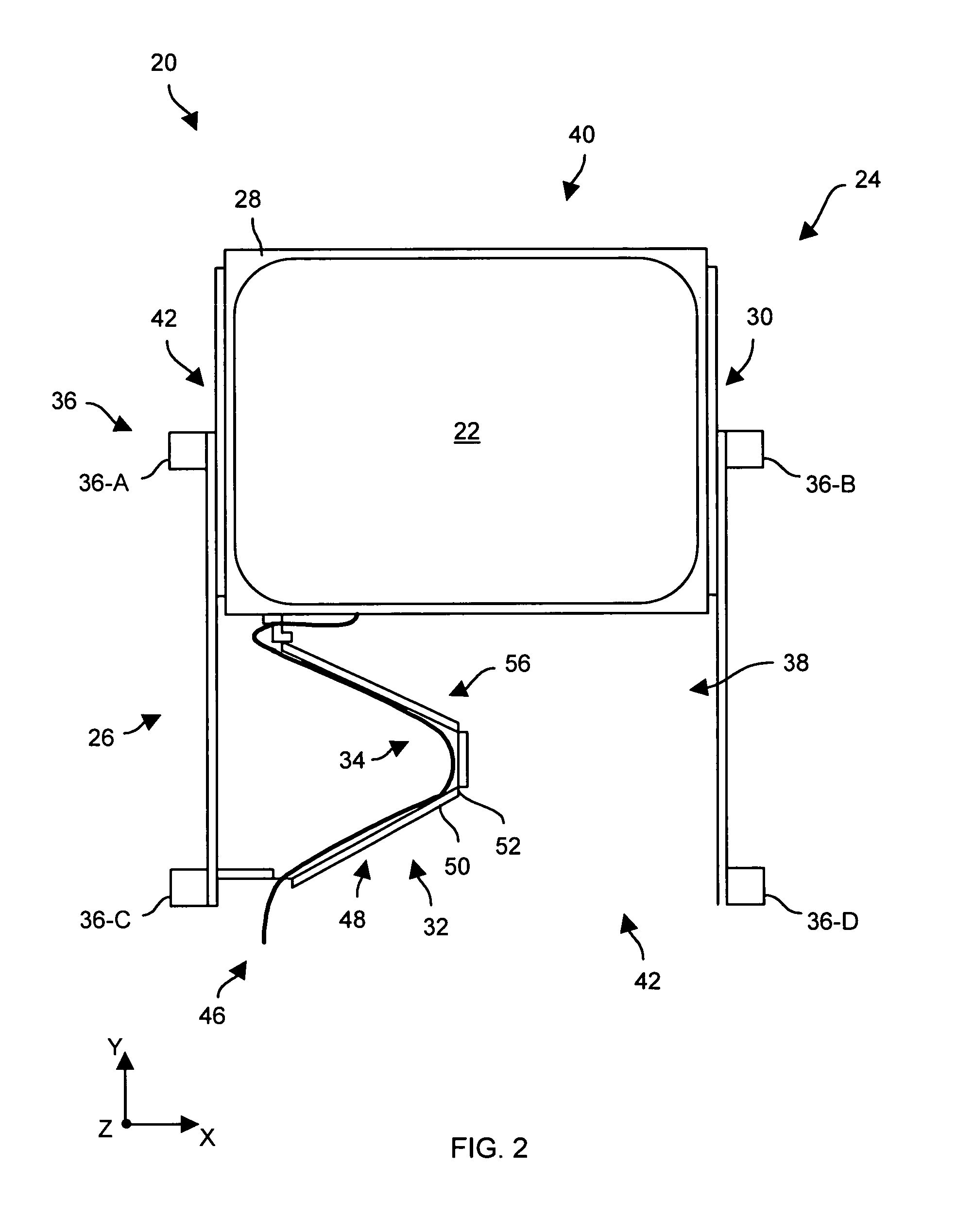
[0021]FIGS. 1 and 2 show cross-sectional top views of an electronic system 20 which is suitable for use by the invention. The electronic system 20 includes, among other things, electronic equipment 22 (e.g., circuitry for a data storage system, a general purpose computer, network equipment, individual electronic devices, specialized electronics, combinations thereo...


PUM


Abstract

An electronic cabinet has an electronic cabinet frame, and a chassis which slidably mounts to the electronic cabinet frame. The chassis is configured to house electronic equipment. The electronic cabinet further has a cable guide which is configured to guide movement of a set of cables which connects to the electronic equipment. The cable guide includes an arm member that defines a set of support portions and a set of hinges. The set of support portions and the set of hinges are integrated together to form a contiguous, unitary body which is configured to support the set of cables. The cable guide further includes a first attachment subsystem to attach the arm member to the electronic cabinet frame, and a second attachment subsystem to attach the arm member to the chassis.

Description

BACKGROUND OF THE INVENTION[0001]A typical electronic cabinet includes a frame, chassis (e.g., housings, card cages, etc.) that mount to the frame to support electronic equipment (e.g., general purpose computer equipment, equipment for a data storage system, network equipment, etc.), and panels (e.g., side panels, doors, front panels, etc.) that attach to the frame to protect the electronic equipment. Some electronic cabinets are available in standard sizes such as a 19-inch equipment rack which enables attachment of standard-sized 19-inch chassis in a vertically-tiered manner within an interior cavity defined by the frame.[0002]One conventional electronic cabinet includes a chassis that mounts onto a set of sliding rails (e.g., guide rollers) fastened to the cabinet frame to enable the chassis to slide out the front of the cabinet from the interior cavity, and back into the interior cavity. Such a cabinet provides convenient access to the electronic equipment housed within the chas...

Claims


Application Information

Patent Timeline
Patent Type & Authority Patents(United States)
IPC IPC(8): H05K7/02H05K7/00
CPCH05K7/1491
Inventor CAVANAUGH, BARRYGOULET, GARY
Owner EMC IP HLDG CO LLC
Why Eureka
Try Eureka