RF antenna array structure

a technology of antenna array and antenna structure, which is applied in the field of antennas, can solve the problems of high transmission line loss, heavy coaxial cable, and high cost of rf transmitter signals, and achieve the effects of low transmission power operation, low installation cost, and significant antenna performance benefits

Active Publication Date: 2006-04-04
LOCKHEED MARTIN CORP
View PDF11 Cites 18 Cited by
  • Summary
  • Abstract
  • Description
  • Claims
  • Application Information

AI Technical Summary

Benefits of technology

[0004]Embodiments of the invention provide a number of technical advantages. Embodiments of the invention may include all, some, or none of these advantages. In one embodiment, multi-layer fiber optic cables are constructed as part of an aircraft structure or an added structure to provide significant benefits in performance, installation, and cost for antennas. This approach may offer a flexible and reconfigurable architecture with embedded fiber optic networks in the skin or structure of platforms. Graceful degradation of system performance and multiple back-up networks are provided in some embodiments of the invention, along with a low observable platform, low transmission power operation, including low probability of intercept (LPI) and power management systems. Optical fibers have no electromagnetic interference susceptibility and emissivity. In one embodiment, an array of antennas may comprise a plurality of smaller arrays that are each adapted to operate within a different frequency band, thus offering system flexibility. For example, more than one beam positioning may be achieved via phase shifting. In one embodiment, an antenna array includes a multipin quick disconnect fiber optic connector for ease in installation and replacement.

Problems solved by technology

However, these copper coaxial cables are often heavy and bulky and, more notably, the RF transmitter signals suffer high transmission line loss in the cables between the power amplifiers and the antenna.

Method used


Image

  • RF antenna array structure
  • RF antenna array structure
  • RF antenna array structure

Examples


Embodiment Construction

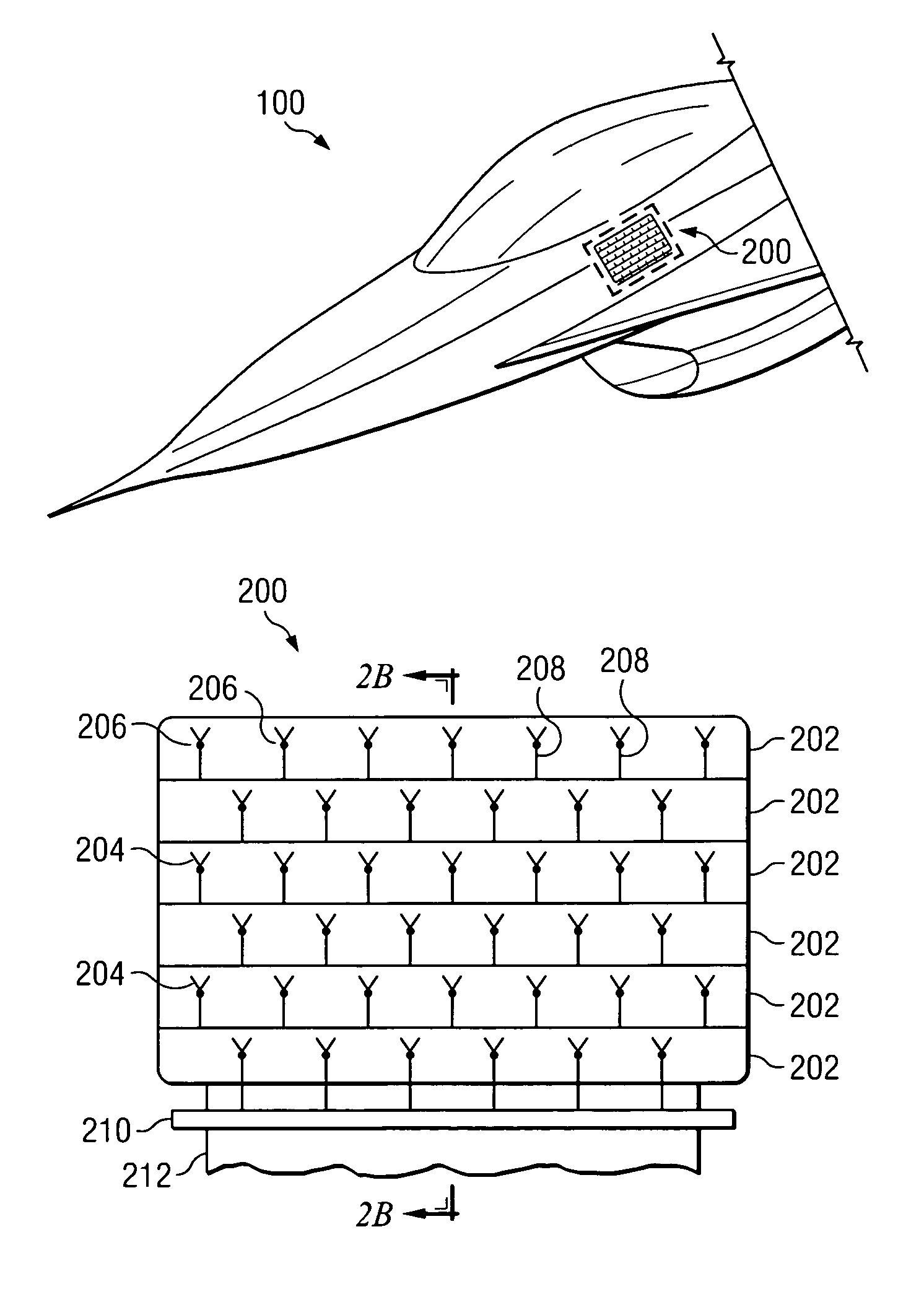
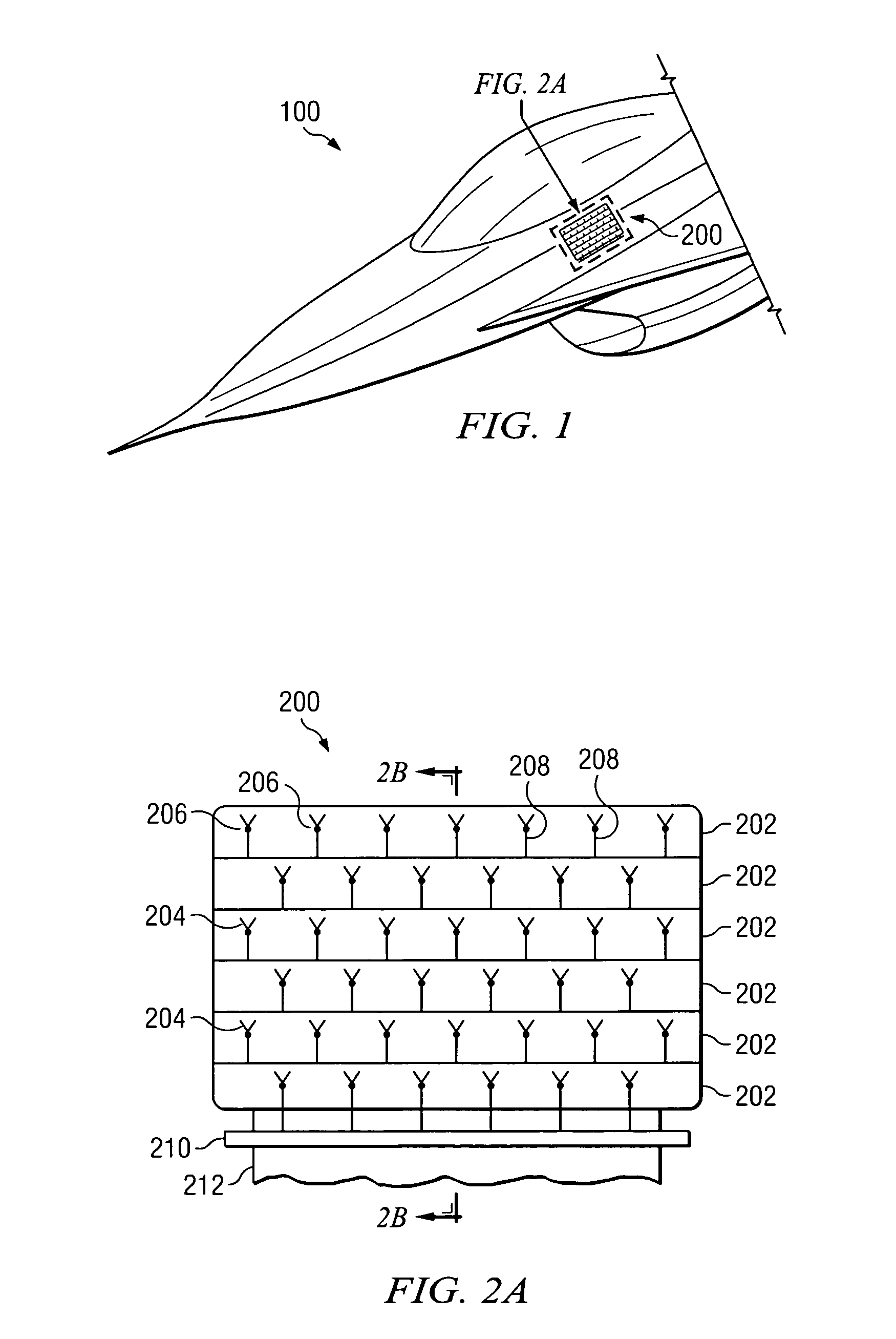
[0011]FIG. 1 is a perspective view of an aircraft 100 incorporating an antenna system 200 according to one embodiment of the present invention. Although antenna system 200 is illustrated in FIG. 1 as being associated with aircraft 100, the present invention contemplates antenna system 200 being associated with other suitable vehicles, devices, and systems. In addition, although antenna system 200 is shown in the fuselage portion of aircraft 100, the present invention contemplates other suitable locations on aircraft 100 for antenna system 200. In the illustrated embodiment, antenna system 200 is a conformal antenna; however, antenna system 200 may be any suitable radio frequency (RF) antenna, such as a slotted array, a spiral, or other suitable antenna. Details of some embodiments of antenna system 200 are described below in conjunction with FIGS. 2A through 3.

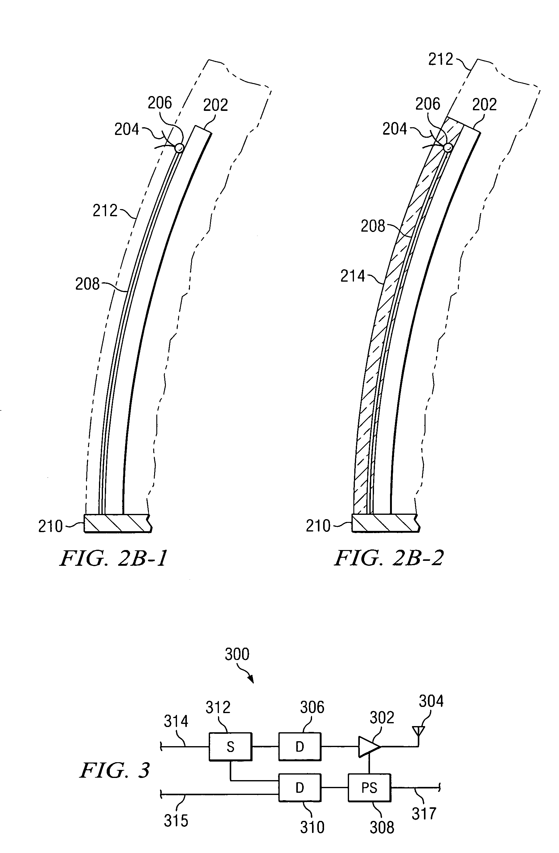
[0012]FIG. 2A is a top view of antenna system 200 according to one embodiment of the invention. In addition, FIGS. 2B-1 and ...


PUM


Abstract

According to one embodiment of the invention, an antenna system includes a substrate, a plurality of antennas formed on the substrate, a plurality of photodiodes formed on the substrate and coupled to respective ones of the antennas, and a plurality of optical fibers coupled to the substrate and coupled to respective ones of the photodiodes.

Description

TECHNICAL FIELD OF THE INVENTION[0001]The present invention relates generally to the field of antennas and, more particularly, to a radio frequency (RF) antenna array structure.BACKGROUND OF THE INVENTION[0002]Antennas are used in many different applications. For example, they are very important in aircraft applications, especially military aircraft. Traditional RF antennas used in aircraft applications utilize copper coaxial cables to transmit RF signals. However, these copper coaxial cables are often heavy and bulky and, more notably, the RF transmitter signals suffer high transmission line loss in the cables between the power amplifiers and the antenna. Consequently, desired transmit signals need to be sufficient enough to compensate the losses during transmit process or use an RF amplifier near the antenna to regain the signal lost during the transmission over the coaxial cable.SUMMARY OF THE INVENTION[0003]According to one embodiment of the invention, an antenna system includes...

Claims


Application Information

Patent Timeline
Patent Type & Authority Patents(United States)
IPC IPC(8): H01Q1/28H01Q3/26
CPCH01Q3/2676
Inventor KIM, KYUNG K.STEWART, II, WILLIAM L.
Owner LOCKHEED MARTIN CORP
Why Eureka
Try Eureka