Method and apparatus for enhancing peak luminance on plasma display panel

a technology of plasma display panel and peak luminance, which is applied in the field of plasma display panel, can solve the problems of power dissipation, difficult voltage modulation of light emitting display luminance, spurious image in moving pictures in the pdp, etc., and achieves the effect of improving the ple method, reducing power dissipation, and high peak luminan

Inactive Publication Date: 2006-04-04
PIONEER CORP
View PDF16 Cites 33 Cited by
  • Summary
  • Abstract
  • Description
  • Claims
  • Application Information

AI Technical Summary

Benefits of technology

[0018]Therefore, an object of the present invention is to improve the PLE method of controlling the number of times of sustaining discharge according to

Problems solved by technology

Because voltage modulation of the light emitting display luminance is difficult in an AC type plasma display device, and it is necessary to change the number of times of light emission for luminance modulation.
However, spurious image occurs in moving pictures in the PDP.
In the case of bright display over the whole panel serface, such as the whole white, therefore, electric power consumption is increased, resulting in a problem of power dissipation and a problem of heat generation of the panel and the circuit.
Although above described PLE method is useful for the plasma display, but it is still insufficient as compared with CRT.
As a result, there is a disadvantage that the peak luminance can not be made sufficiently high by the conventional PDP.
In this ca

Method used


Image

  • Method and apparatus for enhancing peak luminance on plasma display panel
  • Method and apparatus for enhancing peak luminance on plasma display panel
  • Method and apparatus for enhancing peak luminance on plasma display panel

Examples


first embodiment

[0040](First Embodiment)

[0041]The first embodiment of the present invention is explained, referring to Examples.

example 1

[0042](Example 1)

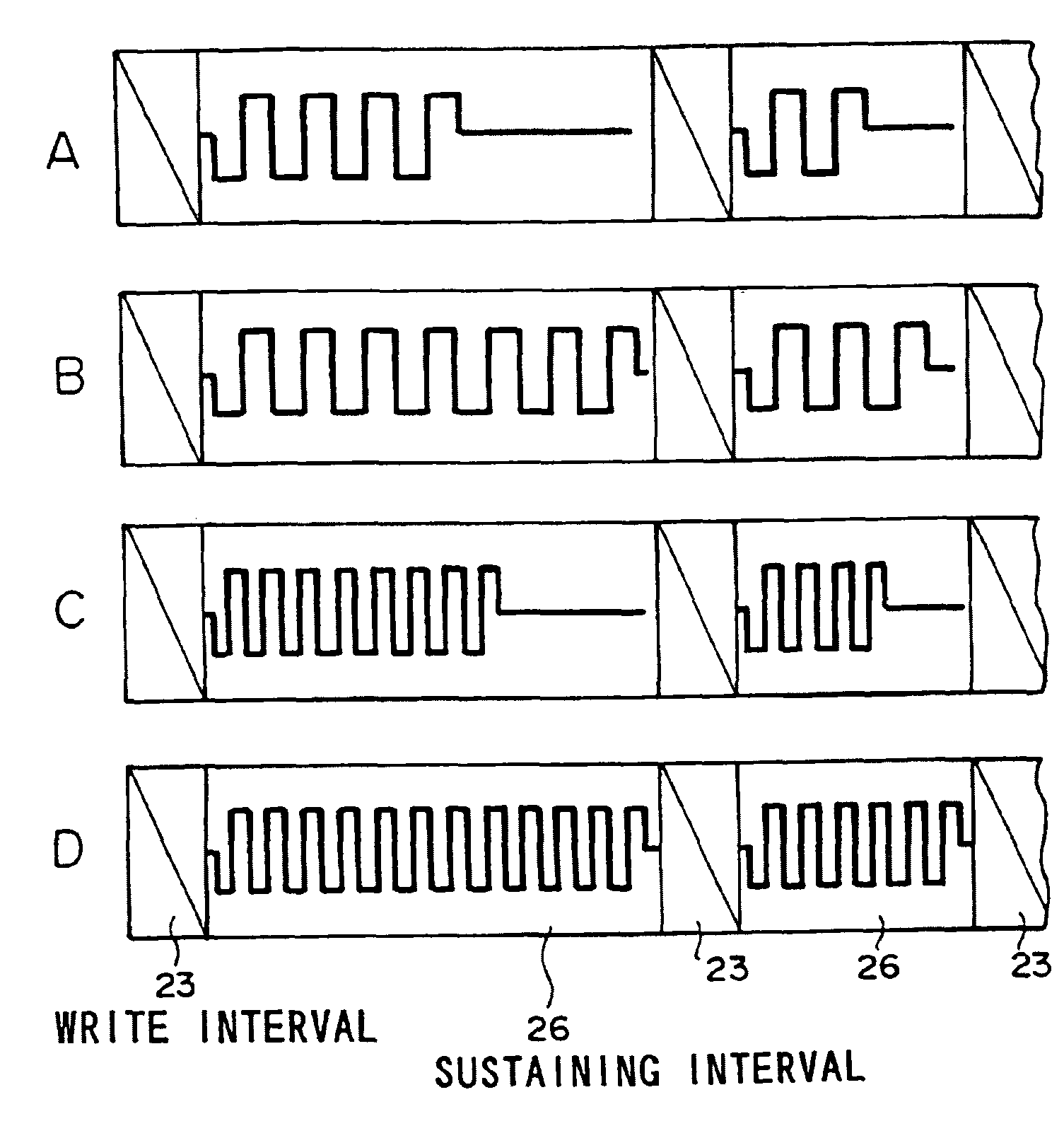
[0043]In Example 1, a color PDP as shown in FIG. 10 is used in order to conduct full color display of 256 gradations. The configuration includes 9 sub-fields provided with redundancy codes. In one frame time of 16.7 ms, the write interval needs 12.5 ms and remaining approximately 4 ms is used as the sustaining interval. By adding image data signals of one frame and averaging them, an average luminance is detected. “Average” used here is an average over one to several pixels with one pixel being formed of a set of R, G and B. Further, eight steps of average peak luminance over the whole display surface of the PDP (APL levels) are determined according to the APL and the maximum luminance. In Example 1, 0 to 12.5% of the maximum luminance is defined as APL level 0, and 12.5% to 25% of the maximum luminance is defined as APL level 1, for brevity. APL level 7 is associated with 87.5% to 100% of the maximum luminance.

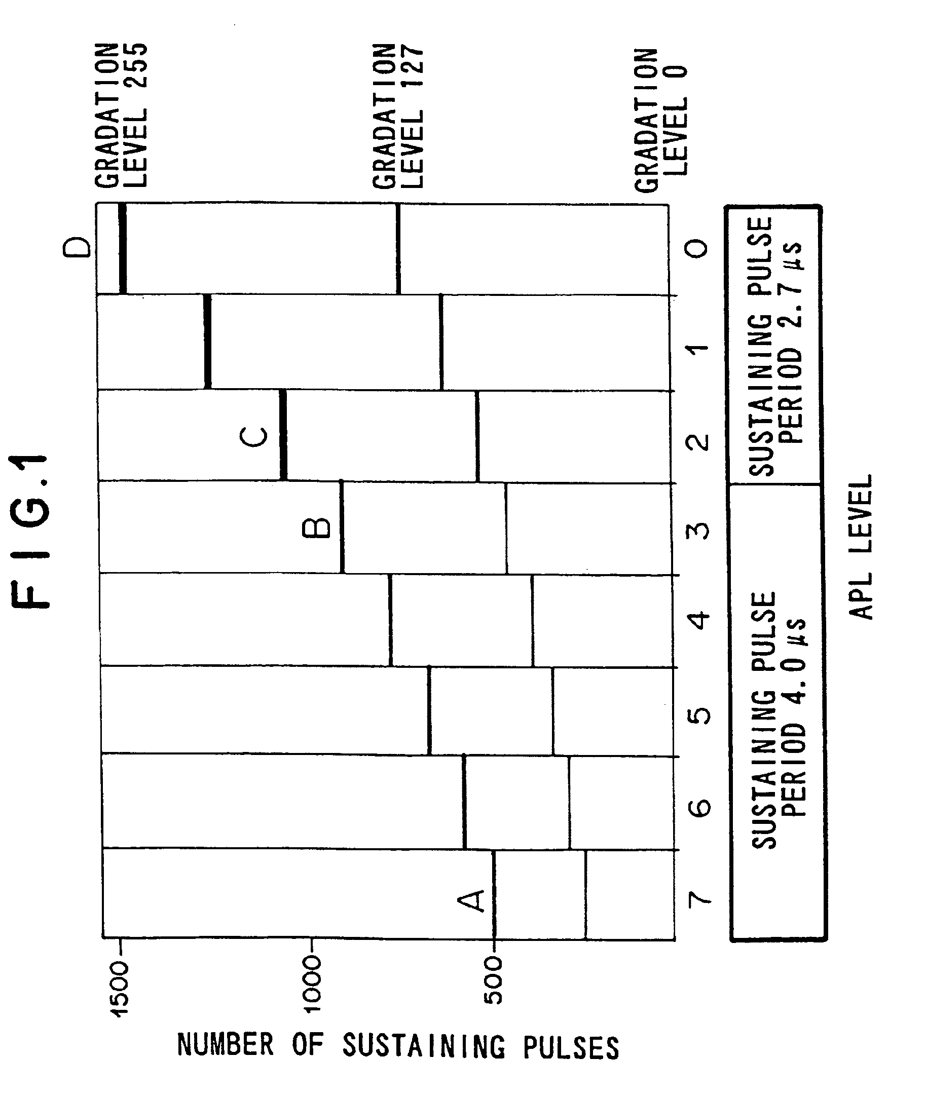
[0044]FIG. 1 shows the total value of sustaining pulses...

example 2

[0049](Example 2)

[0050]In Example 2, there are provided three kinds of sustaining pulse period. However, the set number of sustaining pulse periods depending on the APL level may be further increased to three or more. In this case, a highly peak luminance can be implemented.

[0051]As shown in FIG. 3, the APL level is provided with 16 steps. In the APL levels 0 and 1, the sustaining pulse period is set to 2.0 μs. In the APL levels 2 to 5, the sustaining pulse period is set to 2.7 μs . In the APL levels 6 to 15, the sustaining pulse period is set to be 4.0 μs. When APL is high, Example 2 is similar to the first embodiment. In display of an image having a small APL, the sustaining pulse period is set to a further shorter value, and consequently a number of sustaining pulses equivalent to approximately 2000 which is four times that of APL 15 can be set. As a result, the peak luminance 490 cd / m2 of the white color in the APL level 0 is obtained for the white color luminance 150 cd / m2.

[005...


PUM


Abstract

To provide a plasma display device which implements a peak luminance higher than prior art, reduces the power dissipation, improves the smoothness of gradation display, and conducts clear display suitable especially for TV display. By setting a plurality of APL levels according to the average value of the scene brightness, and by shortening a sustaining pulse period and increasing the number of sustaining pulses of each sub-field in APL levels having small APL, the peak luminance is raised. Further, by making the sustaining pulse period long in APL levels having large APL requiring large discharge light emission power, the light emission efficiency is improved and the maximum power dissipation is reduced. The luminance distribution in the scene when the APL level is small is detected. On the basis of that information, setting of the number of sustaining pulses and the sustaining pulse period is changed in the same APL level. As a result, the peak luminance is increased, and the gradation smoothness in the dark scene is improved.

Description

BACKGROUND OF THE INVENTION[0001]1. Technical Field of the Invention[0002]The present invention relates to a plasma display panel (PDP). In particular, the present invention relates to the PDP, wherein power dissipation is reduced, display luminance is increased, and gradation is displayed smoothly by controlling the number and period of pulses for sustaining discharge (SD) in plasma.[0003]2. Description of the Prior Art[0004]In the plasma display, fluorescent substance is exited by ultraviolet light generated by gaseous discharge, thereby making the fluorescent substance emit light. The plasma display is applied to large scene TV display and information display.[0005]A PDP structure as shown in FIG. 10A is a top view of a back substrate with a part broken away. FIG. 10B is a sectional view of a front substrate, and FIG. 10C is a sectional view of the back substrate. Front substrate 100 acting as a display surface has a plurality of transparent electrodes 3 and a plurality of narrow...

Claims


Application Information

Patent Timeline
IPC IPC(8): G09G3/28G09G3/20G09G3/288G09G3/291G09G3/293G09G3/294
CPCG09G3/2944G09G3/2022G09G2360/16G09G2330/021G09G2320/0233
Inventor NUNOMURA, KEIJISANO, YOSHIOAKIYAMA, TOSHIYUKIYAMADA, HACHIRO
Owner PIONEER CORP
Why Eureka
Try Eureka