Pixel circuit including a first switching element section showing a saturation characteristic and a second switching element section showing a linear characteristic and display device including the pixel circuit

a pixel circuit and switching element technology, applied in the field of configuration of pixel circuits, can solve the problems of limiting the grayscale display range and higher peak luminance, and achieve the effect of higher peak luminan

Active Publication Date: 2014-11-04
SHARP KK
View PDF23 Cites 3 Cited by
  • Summary
  • Abstract
  • Description
  • Claims
  • Application Information

AI Technical Summary

Benefits of technology

[0018]The configuration makes it possible to provide a pixel circuit which can generate higher peak luminance while sufficiently securing a voltage range which causes an appropriate normal grayscale display within a predetermined driver voltage output range.
[0052]According to the invention, it is possible to provide a display device which can generate higher peak luminance while sufficiently securing a voltage range which causes an appropriate normal grayscale display within a predetermined driver voltage output range.

Problems solved by technology

This will limit a grayscale display range which causes higher peak luminance.

Method used


Image

  • Pixel circuit including a first switching element section showing a saturation characteristic and a second switching element section showing a linear characteristic and display device including the pixel circuit
  • Pixel circuit including a first switching element section showing a saturation characteristic and a second switching element section showing a linear characteristic and display device including the pixel circuit
  • Pixel circuit including a first switching element section showing a saturation characteristic and a second switching element section showing a linear characteristic and display device including the pixel circuit

Examples


example 1

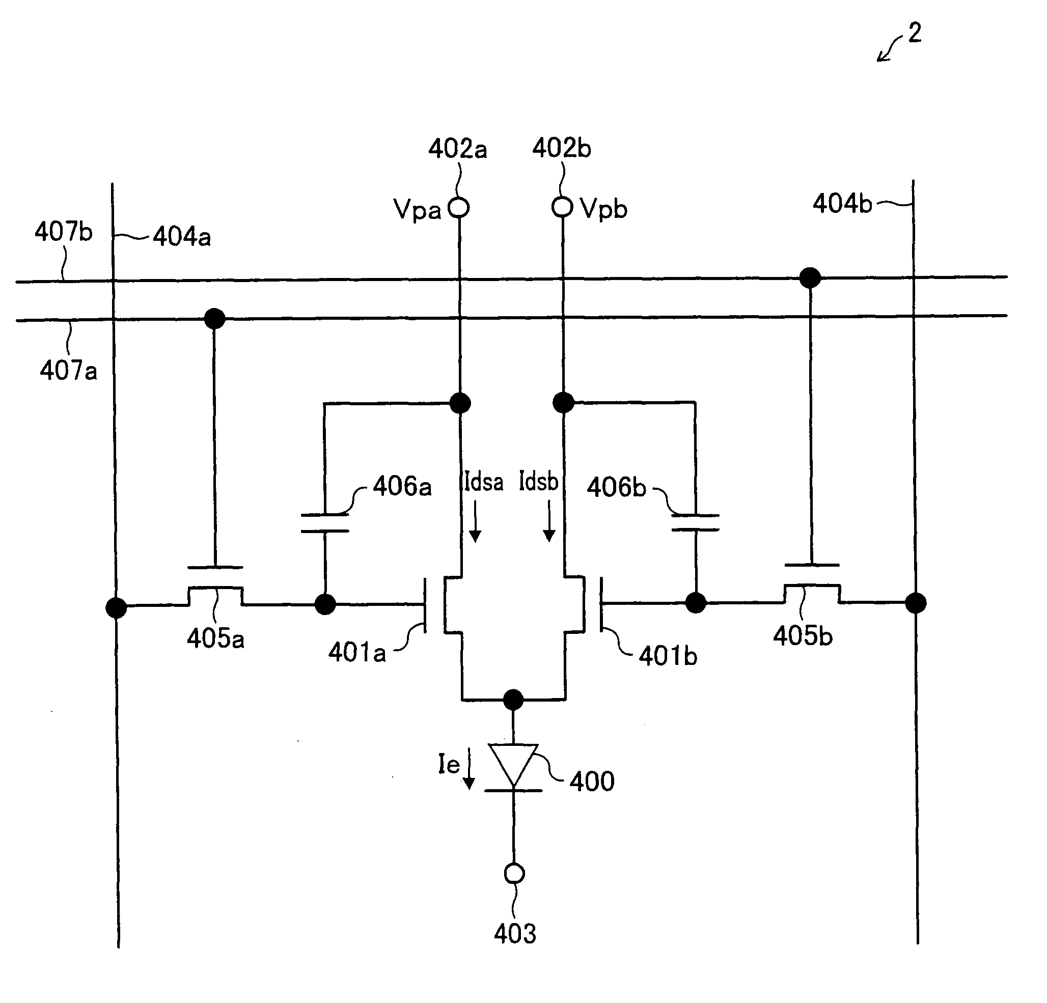
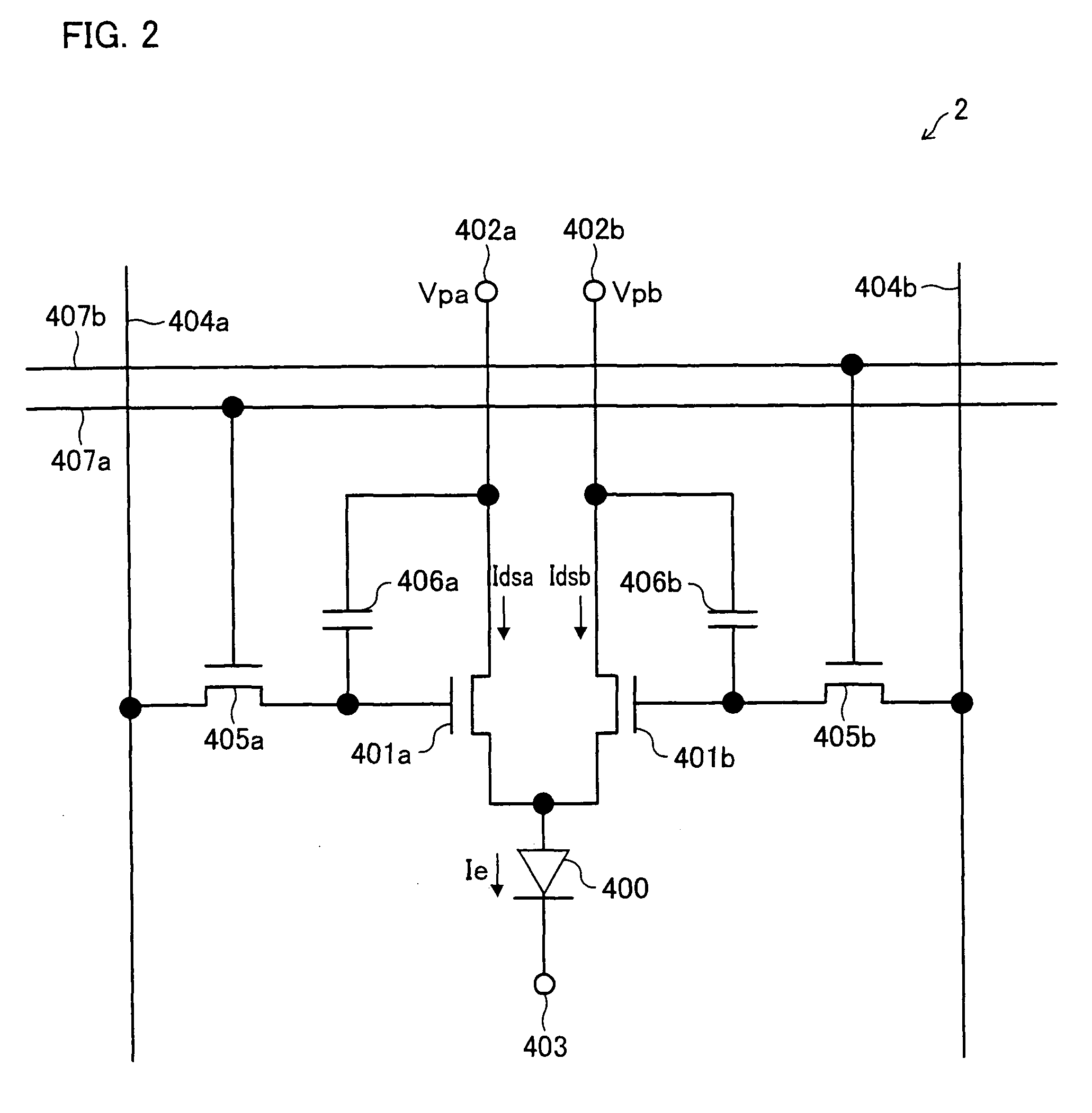
[0164]FIG. 2 illustrates a circuit configuration of a pixel circuit 2 which is one example of the pixel circuit 1. According to FIG. 2, a TFT 401a, a TFT 401b, a light emitting element 400, a current supply voltage line 402a, a current supply voltage line 402b, and a common voltage supply line 403 correspond to the first semiconductor element 340, the second semiconductor element 305, the light emitting element 306, the power supply electrode 301, the power supply electrode 302, and the common electrode 303 shown in FIG. 1, respectively. In Example 1, it is assumed that all the TFTs used in the pixel circuit 2 are P-type TFTs.

[0165]One of input terminal of the light emitting element 400 is connected to drain terminals of the respective TFTs 401a and 401b one of which is connected in shunt with the other. The light emitting element 400 receives a light emitting current Ie which is a sum of a drain current Idsa of the TFT 401a and a drain current Idsb of the TFT 401b. Source terminals...

example 2

[0180]FIG. 4 illustrates a circuit configuration of a pixel circuit 3 which is another example of the pixel circuit 1. Unlike the pixel circuit 2 shown in FIG. 2, in the pixel circuit 3 each of a storage capacitor, a data signal line, and a selection signal line is shared. According to FIG. 4, a TFT 601a, a TFT 601b, a light emitting element 600, a current supply voltage line 602a, a current supply voltage line 602b, and a common voltage supply line 603 correspond to the first semiconductor element 304, the second semiconductor element 305, the light emitting element 306, the power supply electrode 301, the power supply electrode 302, and the common electrode 303 shown in FIG. 1, respectively. It is assumed that all the TFTs used in the pixel circuit 3 are P-type TFTs.

[0181]One of input terminal of the light emitting element 600 is connected to drain terminals of the respective TFTs 601a and 601b one of which is connected in shunt with the other. The light emitting element 600 recei...

example 3

[0231]FIG. 14 illustrates a structure of a display device in which the present invention is incorporated. The display device shown in FIG. 14 includes a source driver circuit (grayscale signal supply circuit section) 1406, a gate driver circuit (pixel selection signal circuit section) 1407, and a pixel region 1401 in which a plurality of pixel circuits each shown in FIG. 4 are provided in a matrix manner.

[0232]In the pixel region 1401, a grayscale signal line (data signal line) 1402 (604), a line selection signal line (scan signal line) 1403 (607), a power supply line (first power supply line) 1404a (602a), a power supply line (second power supply line) 1404b (602b), and a power supply line 1405 (603) are provided all together and extend outside the pixel region 1401. Note that the parenthesized numerals and symbols indicate reference signs of the corresponding components shown in FIG. 4.

[0233]The source driver circuit 1406 provided outside the pixel region 1401 includes: a pluralit...


PUM


Abstract

A pixel circuit of at least one embodiment of the present invention includes: a display element whose light emitting luminance is controlled by a supplied current; at least one first switching element section whose output current characteristic shows a saturation characteristic in response to an input variable serving as a grayscale signal; and at least one second switching element section whose output current characteristic shows a linear characteristic in response to an input variable serving as a grayscale signal. A first current supply line which outputs a current determined by the first switching element section and a second current supply line which outputs a current determined by the second switching element section are combined, and then succeeded by a current supply line of the display element. This makes it possible to provide a pixel circuit and a display device which can generate higher peak luminance while sufficiently securing a voltage range which causes an appropriate normal grayscale display within a predetermined driver voltage output range.

Description

TECHNICAL FIELD[0001]The present invention relates to an active matrix display device such as an organic electroluminescence (hereinafter, referred to as “organic EL”) display device. Specifically, the present invention relates to a configuration of a pixel circuit and a grayscale driving method of the pixel circuit.BACKGROUND ART[0002]According to a pixel cell of an active matrix organic EL display device, a series circuit is provided between (i) a power supply electrode 103 via which a power supply voltage Vp is supplied and (ii) a common electrode 104 via which a power supply voltage Vc is supplied (see FIG. 11). In the series circuit, a semiconductor switching element 106 is electrically connected with an organic EL thin film 108 serving as light emitting element. Moreover, a grayscale signal VD is supplied via a data signal line 101 to a gate terminal of the semiconductor switching element 106 so that the semiconductor switching element 106, which controls a light emitting curr...

Claims


Application Information

Patent Timeline
Patent Type & Authority Patents(United States)
IPC IPC(8): G09G3/30G09G3/32H01L27/32
CPCG09G3/3233G09G2310/0262H01L27/3262G09G2300/0852H10K59/1213
Inventor YAMANAKA, SHIGETSUGU
Owner SHARP KK
Why Eureka
Try Eureka