Multi-output power supply design system

a power supply design and multi-output technology, applied in the direction of cad circuit design, program control, instruments, etc., can solve the problems of power supply and controller complexity, power supply and power supply requirements of electrical systems becoming ever more demanding, and existing tools and techniques for designing single-output power supplies do not address these challenges

Inactive Publication Date: 2006-04-04
HERCULES TECH GROWTH CAPITAL
View PDF1 Cites 57 Cited by
  • Summary
  • Abstract
  • Description
  • Claims
  • Application Information

AI Technical Summary

Benefits of technology

[0016]For any target implementation, software suitable for execution on a host system CPU is generated that allows the control and monitoring of the generated design. A feature of the generated software is that it has virtually the same interface regardless of the target implementation, enabling early development of upper layers of system software using physical embodiments different from that of the final system. When the final physical embodiment becomes available, the upper software layers require little or no modification.

Problems solved by technology

The power requirements of electrical systems are becoming ever more demanding.
As a result, power supplies and their controllers are becoming increasingly complex.
One of the trends challenging designers is the requirement for more regulated output voltages within the same system.
In the case of a multi-output power supply, i.e., a power supply providing multiple regulated output voltages, the designer is challenged not only by the problems posed by the control of multiple power stages, but also by the problems of interactions among controllers.
Existing tools and techniques for designing single-output power supplies do not address these challenges.
In the case of large systems, the use of uninterruptible backup power supplies is increasingly common.
In the case of a multi-input power supply, i.e., a power supply incorporating two or more alternate input power sources, the designer is challenged not only by the requirement for “graceful” switching between or among input power sources, but also by the widening range of input voltages to the power stages.
In the case of distributed power systems, the system designer is challenged to implement a modular, yet cost-effective power system architecture.
But there are many barriers to achieving this level of integration.
One major barrier to integration is the large number of power supply topologies, including: buck, boost, buck-boost, fly-back, fly-forward, isolated, non-isolated, DC to DC, DC to AC, and AC to AC, etc.
This proliferation of devices, however, becomes a barrier of its own, as the rapidly growing number of different device types will create substantial manufacturing disadvantages for both customers and vendors.
A barrier to this is that controllers have historically been designed using analog circuit techniques, which are generally difficult to integrate into system-level ASIC design methodologies that are primarily digital in nature.
And this problem is further compounded by a general lack of available personnel that combine power systems and mixed-signal silicon design expertise.
The lack of personnel with the required power systems and mixed-signal design experience remains as a barrier.

Method used


Image

  • Multi-output power supply design system
  • Multi-output power supply design system
  • Multi-output power supply design system

Examples


Embodiment Construction

[0027]In the following descriptions, numerous specific details are set forth, such as the specific rendering of the implementation, in order to provide a thorough understanding of the present invention. It will be apparent, however, to one skilled in the art that the present invention may be practiced without these specific details. In other instances, well-known circuits, control logic, and design and coding techniques have not been shown in detail, in order to avoid unnecessarily obscuring the present invention.

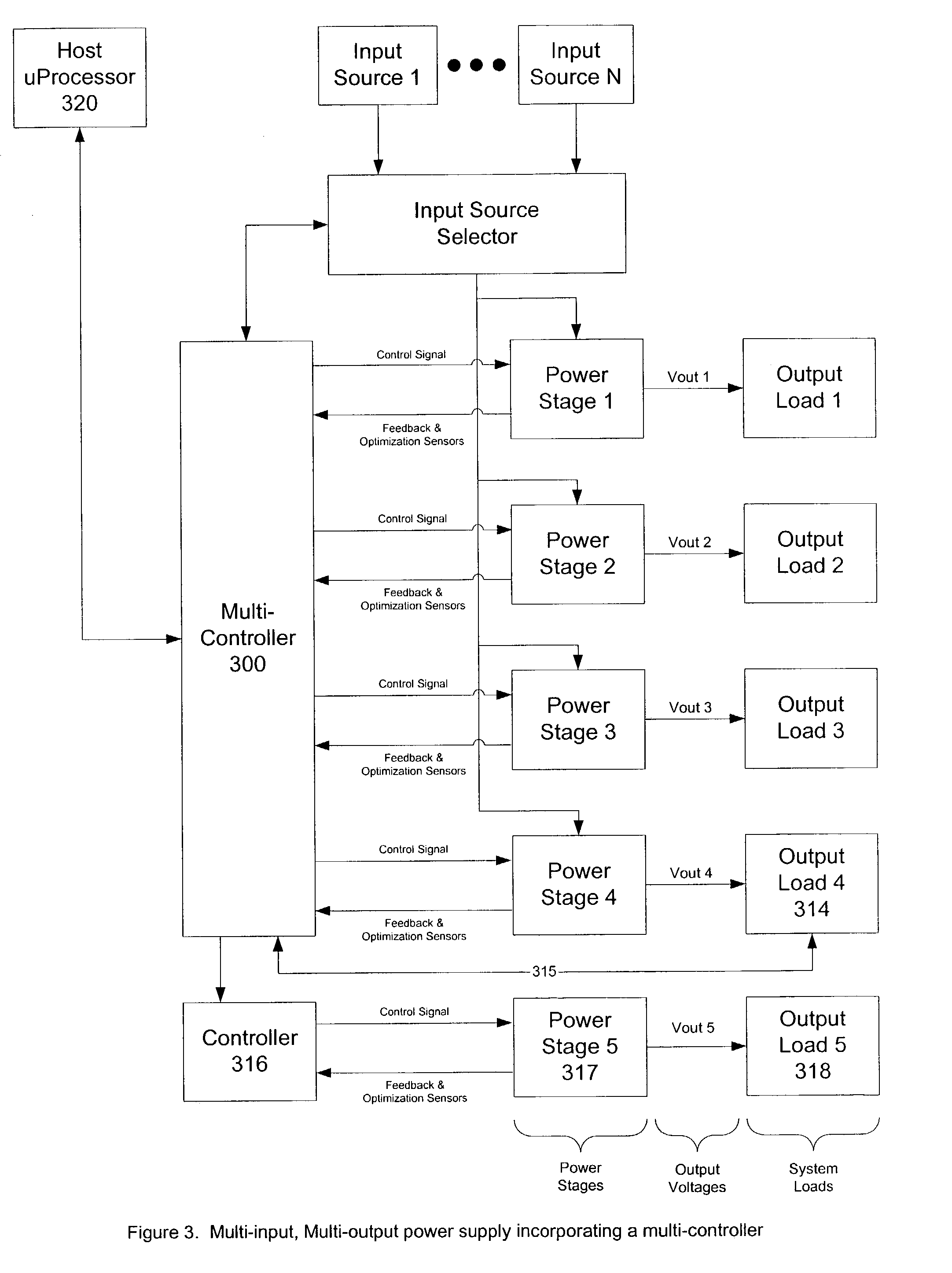
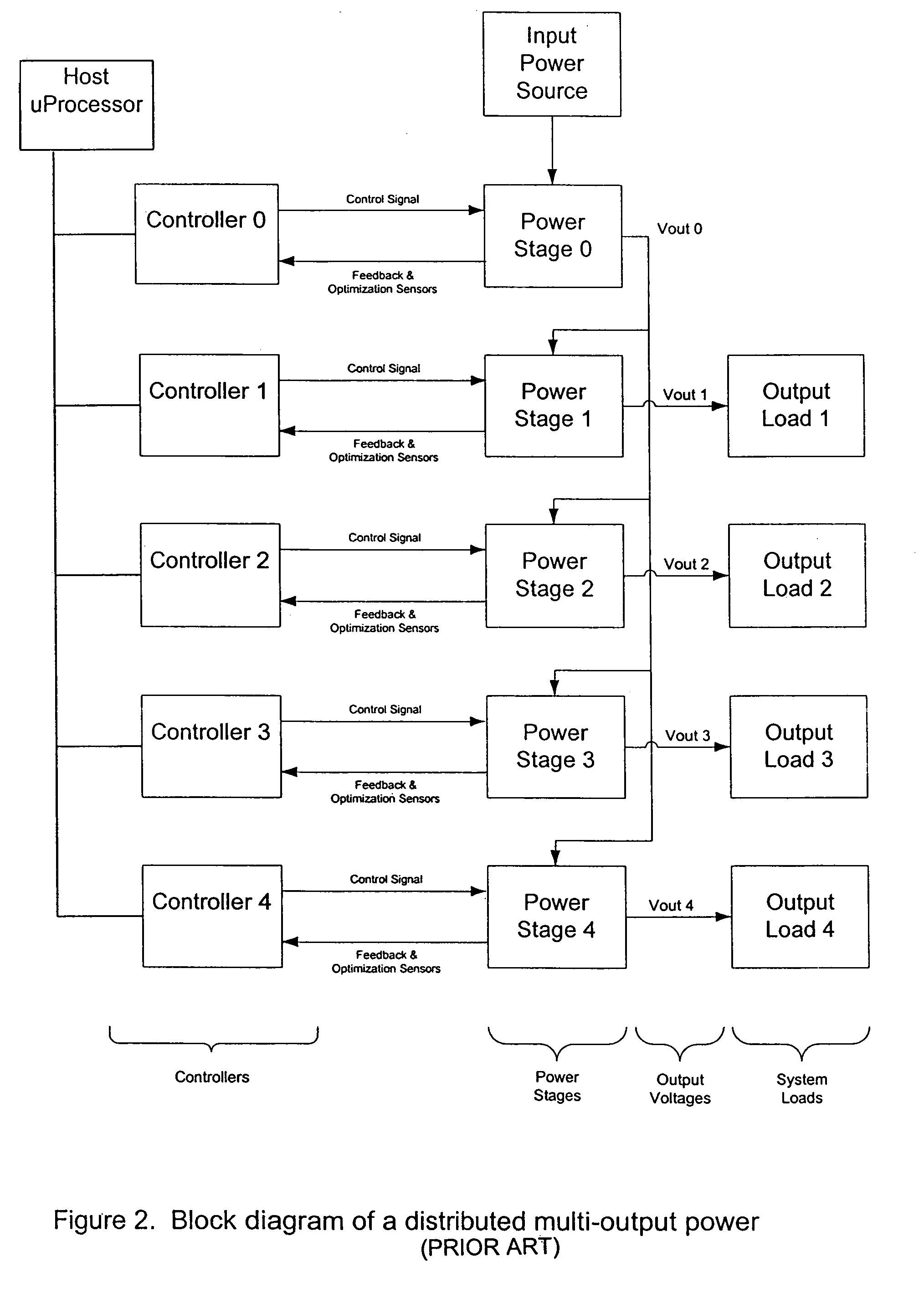
[0028]Multi-Output Power Supply Design

[0029]Multi-output power supply designs can be classified under two headings. The first classification, referred to simply as multi-output power supplies, includes power supplies comprising multiple power stages, where each power stage provides power to a load which is not a power supply. The second classification, referred to as distributed multi-output power supplies, includes power supplies comprising multiple power stages, where at ...


PUM


Abstract

A tool is described to aid in the design and verification of multi-input, multi-output power supply systems. The designer describes the system requirements and constraints to the tool, which allows an iterative exploration of various alternative designs that satisfy the requirements and constraints. Alternative designs may comprise different power supply topologies, multiple controllers or multi-controllers, or configurable controllers that implement the power supply system. The tool generates a design for a power supply system that is reconfigurable to allow for performance optimization. The power supply system is configurable automatically according to a digital control signal. The digital control signal comprises configuration data which establishes the structure of the power supply system, and which determines the output power conditions of the power source. The different conditions generated by configuration data comprise output voltage, sequencing information, current, topology, and other operational conditions such as overload protection.

Description

FIELD OF INVENTION[0001]This patent relates to the tools and techniques used to design power supplies and power supply controllers.BACKGROUND[0002]The power requirements of electrical systems are becoming ever more demanding. To maximize energy efficiency, power density, and system serviceability, the power system designer is being asked to provide increased functionality and improved performance at minimal cost. As a result, power supplies and their controllers are becoming increasingly complex.[0003]One of the trends challenging designers is the requirement for more regulated output voltages within the same system. A typical battery powered personal digital assistant (PDA) may reasonably be expected to provide four or more different voltages, each with dramatically different dynamic requirements. One supply may service the CPU, another, the display, another the touch screen and another an RF transceiver. In the case of a multi-output power supply, i.e., a power supply providing mu...

Claims


Application Information

Patent Timeline
Patent Type & Authority Patents(United States)
IPC IPC(8): G06F17/50G06F9/45G06F9/455H02M
CPCG06F17/50G06F2217/86G06F2217/78G06F30/00G06F2117/08G06F2119/06
Inventor COLLMEYER, ARTHURSZEPESI, THOMASWONG, DICKSONSAMUELS, ALLEN
Owner HERCULES TECH GROWTH CAPITAL
Why Eureka
Try Eureka