
Partial reconfiguration of a programmable gate array using a bus macro

a programmable gate array and macro technology, applied in the field of bus macro, can solve the problems of not being able to fully implement partial reconfiguration for all cases, and being difficult to program, and affecting the implementation of partial reconfiguration

Inactive Publication Date: 2006-04-04
XILINX INC
View PDF7 Cites 51 Cited by
  • Summary
  • Abstract
  • Description
  • Claims
  • Application Information

AI Technical Summary

Problems solved by technology

But, obstacles remain in connection with fully implementing partial reconfiguration for all cases.
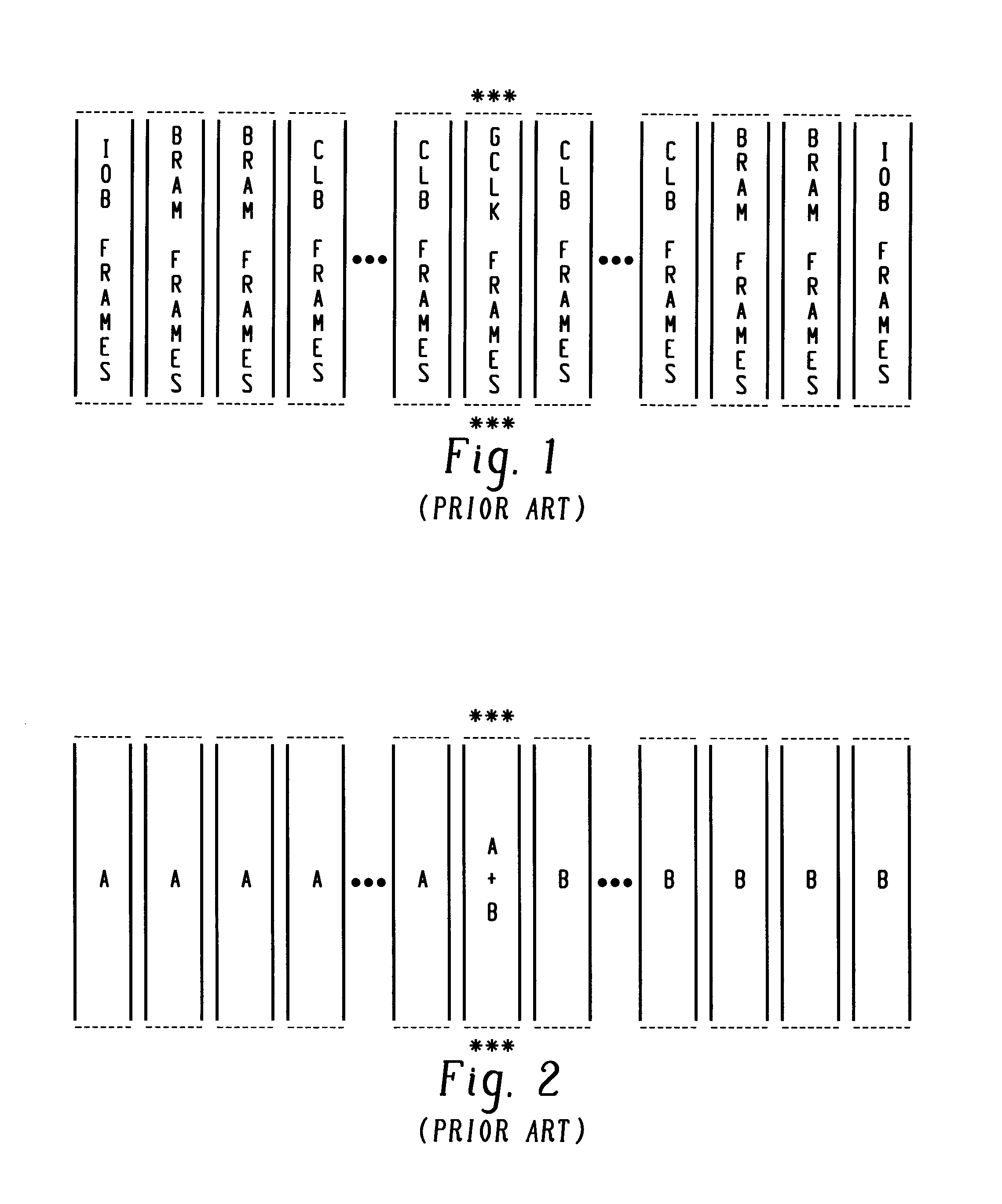
With the current programming structure of FPGAs, it is a rather complex and difficult operation to program partially a separate and independent area of CLB columns for a particular design which includes interdesign routing.
So, if communication to another design is attempted through partial reconfiguration of a particular design area, the routing will vary and may not connect correctly with existing interdesign routing.
Accordingly, for partial reconfiguration, there is a problem that arises when multiple designs are programmed into an FPGA with different interdesign routing structures as will be explained in greater detail herebelow.
However, except for special cases as explained herein above, partial reconfiguration presents problems for designs with interdesign routing.
For example, if a new design variant A2 is loaded into the FPGA by partial reconfiguration, it over-writes the previous design variant A1 that was stored in the columns of the left hand side thereof, thus possibly causing a routing disconnect between designs A and B. The same procedure may be performed for the variants of design B in the right hand columns with the same problem possible.
In practice, partially reconfiguring the FPGA in this manner is not easily achievable due primarily to the software limitations accommodating programming of the frames of the interdesign routing as mentioned above.

Method used


Image

  • Partial reconfiguration of a programmable gate array using a bus macro
  • Partial reconfiguration of a programmable gate array using a bus macro
  • Partial reconfiguration of a programmable gate array using a bus macro

Examples


Embodiment Construction

/ ********************************************************* \***Module  : designA.v****Description : Design using Bus Macro instantiation.**Design is intended to be placed and routed on the left**half of a Xilinx Virtex V50 device.****The basic function of A allows a 4-bit incrementer**to be either loaded from off-chip, loaded from the**B (right-side) design, or simply incremented.***\ ********************************************************* / ‘timescale lns / 10psmodule designA (clockA_in, loadA, loadB, triA, data_inA,data_outA);input clockA_in, loadA, loadB, triA;input [3:0] data_inA;output [3:0] data_outA;wire [3:0] tribusA;wire clockA_buf;wire [3:0] data_inB, tribusB;wire [3:0] data_outB;reg [3:0] counter;assign tribusA = { triA, triA, triA, triA };assign data_inB = 4'b1111;assign tribusB = 4′b1111;IBUFG ibufgA (.I(clockA_in), .O(clockA_buf));BUFG bufgA (.I(clockA_buf), .O(clockA));always @(posedge clockA)if (loadA) counter else if (loadB) counter else counter busmacro bus4bit (...


PUM


Abstract

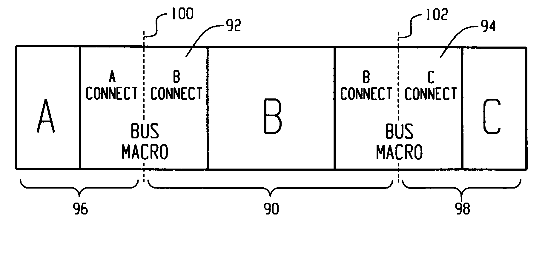
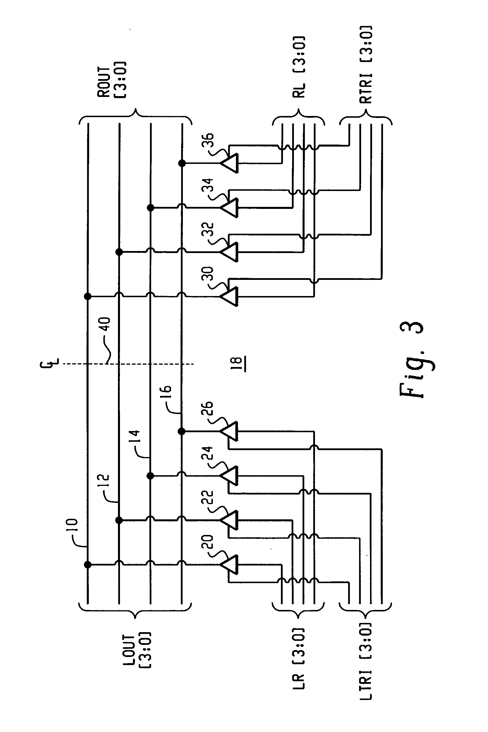
A bus macro for use as a routing resource for partial reconfiguration of a field programmable gate array (FPGA) with a design that has interdesign routing with at least one other design programmed into the FPGA comprises: at least one row of bus lines disposed within the FPGA between at least two design areas; a first set of gates disposed within the FPGA for controlling a routing of signals over the at least one row of bus lines from a first design area to a second design area of the FPGA according to a first routing configuration embedded in the first design area; and a second set of gates disposed within the FPGA for controlling a routing of signals over the at least one row of bus lines from the second design area to the first design area of the FPGA according to a second routing configuration embedded in the second design area. A method of partially reconfiguring a field programmable gate array (FPGA) with at least one design that has interdesign routing with at least one other design programmed into the FPGA is also disclosed utilizing at least one bus macro.

Description

FIELD OF THE INVENTION[0001]The present invention is directed to the partial reconfiguration of programmable gate arrays, in general, and more particularly, to a bus macro and a method of partially reconfiguring a programmable gate array having a plurality of circuit designs which communicate among each other through routing between their separate and independent areas of the array using a bus macro.BACKGROUND OF THE INVENTION[0002]In the past, field programmable gate array (FPGA) architectures accommodated only configuration of the entire array. Accordingly, with each change in a design and / or the addition of a design, a whole new bit stream had to be generated for configuring or programming the whole FPGA. Recently, however, new FPGA architectures were developed, like the Virtex® series manufactured by Xilinx®, for example, that accommodated a partial reconfiguration even down to an information frame level. For a more detailed understanding of configuration and partial configurati...

Claims


Application Information

Patent Timeline
IPC IPC(8): G06F17/50H03K19/177
CPCH03K19/17736H03K19/17796H03K19/17756
Inventor CAMILLERI, NICOLAS JOHNMCGETTIGAN, EDWARD S.
Owner XILINX INC
Learn More