Axial loaded seal system with a static L-seal

a static lseal and seal system technology, applied in brake systems, light and heating equipment, machines/engines, etc., can solve the problems of increasing leakage path, increasing the possibility of leakage in the seal, and increasing the sensitivity of the o-ring, so as to increase the leakage path, and reduce the risk of damage

Active Publication Date: 2006-04-11
EDWARDS VACUUM LLC
View PDF29 Cites 4 Cited by
  • Summary
  • Abstract
  • Description
  • Claims
  • Application Information

AI Technical Summary

Benefits of technology

[0008]Despite the efficacy of a radially loaded dynamic ring seal that is axially loaded by a combination of load rings, static seal rings and wave springs, extreme changes in temperature in cryogenic refrigerators can cause thermal contraction of the seal rings which creates both axial and radial movement that allow leakage. In the axial loaded seal system, the “Z-cut” and the shorter backup rings still create a very small leak path. If the backup rings move during operation, delta pressure increases across the displacer, or the seal wears over time, the leak path will increase. Also, the axial load applied by the spring can potentially be overcome if differential pressure increases across the displacer. Furthermore, while the use of elastomer O-rings allows a secure radial fit since the O-rings have some elasticity, that same property makes O-rings more sensitive to damage, thus increasing the possibility of leakage in the seal.
[0009]The present invention uses a static seal ring with a flat axial facing surface over a dynamic seal ring. In one embodiment, polymer surfaces of a static seal ring and a dynamic seal ring allow movement between the two seal rings, thus minimizing a lock of the dynamic seal ring's radial movement through friction. In addition, the polymer seal ring also provides more flexibility than a metal ring with regard to fit around a displacer, while providing more rigidity and durability than an elastomer O-ring.
[0011]The static seal ring can have an L-shaped cross section (“L-ring”). A load ring can also be placed between the wave spring and the L-ring to distribute an axial load onto the static and dynamic seals. Alternatively, the static seal ring can be a flanged load ring that has a flange that abuts the piston body. Both the static seal and the dynamic seal can have flat abutting axial surfaces that allow a low friction movement between the static seal and dynamic seal.
[0012]The static polymer seal ring contracts to form a seal to the outer diameter of the displacer within the groove, restricting the flow path through the Z-cut to the inner diameter of the split seal to the opposing differential pressure region. Further, it creates a second sealing surface on an axial face of the dynamic seal and locks the axial force on the split seal independent of the spring and eliminates the spring from potentially lifting while operating at cryogenic temperatures. The use of these static polymer seal rings can relax the needed tight tolerances on the split seal, back-up ring height and load ring surface finish and could even eliminate the need for a dimpled seal.
[0015]Another embodiment of the invention includes a refrigerator having a cylinder and the piston is a displacer mounted within the cylinder. The displacer includes a body with a circumferential groove, two polymer seal rings, and a spring. The groove includes a first groove wall and a second groove wall where the two seal rings are located against the first groove wall, the first seal ring forms a dynamic seal and the second ring forms a static seal. The spring is located between the seal rings and the second groove wall, the spring axially loading the seal rings. A load ring can also be placed between the spring and the static seal to help uniformly distribute the axial load on the static seal. The body can include a sleeve mounted on the body where the sleeve forms the first groove wall and the body forms the second groove wall. The spring can include a wave spring which axially loads the seal ring. The dynamic seal ring can include a split seal ring having at least one radial spring mounted within the split seal ring to create a radial force of the split seal ring against the cylinder.

Problems solved by technology

Despite the efficacy of a radially loaded dynamic ring seal that is axially loaded by a combination of load rings, static seal rings and wave springs, extreme changes in temperature in cryogenic refrigerators can cause thermal contraction of the seal rings which creates both axial and radial movement that allow leakage.
If the backup rings move during operation, delta pressure increases across the displacer, or the seal wears over time, the leak path will increase.
Furthermore, while the use of elastomer O-rings allows a secure radial fit since the O-rings have some elasticity, that same property makes O-rings more sensitive to damage, thus increasing the possibility of leakage in the seal.

Method used


Image

  • Axial loaded seal system with a static L-seal
  • Axial loaded seal system with a static L-seal
  • Axial loaded seal system with a static L-seal

Examples


Embodiment Construction

[0026]A description of preferred embodiments of the invention follows.

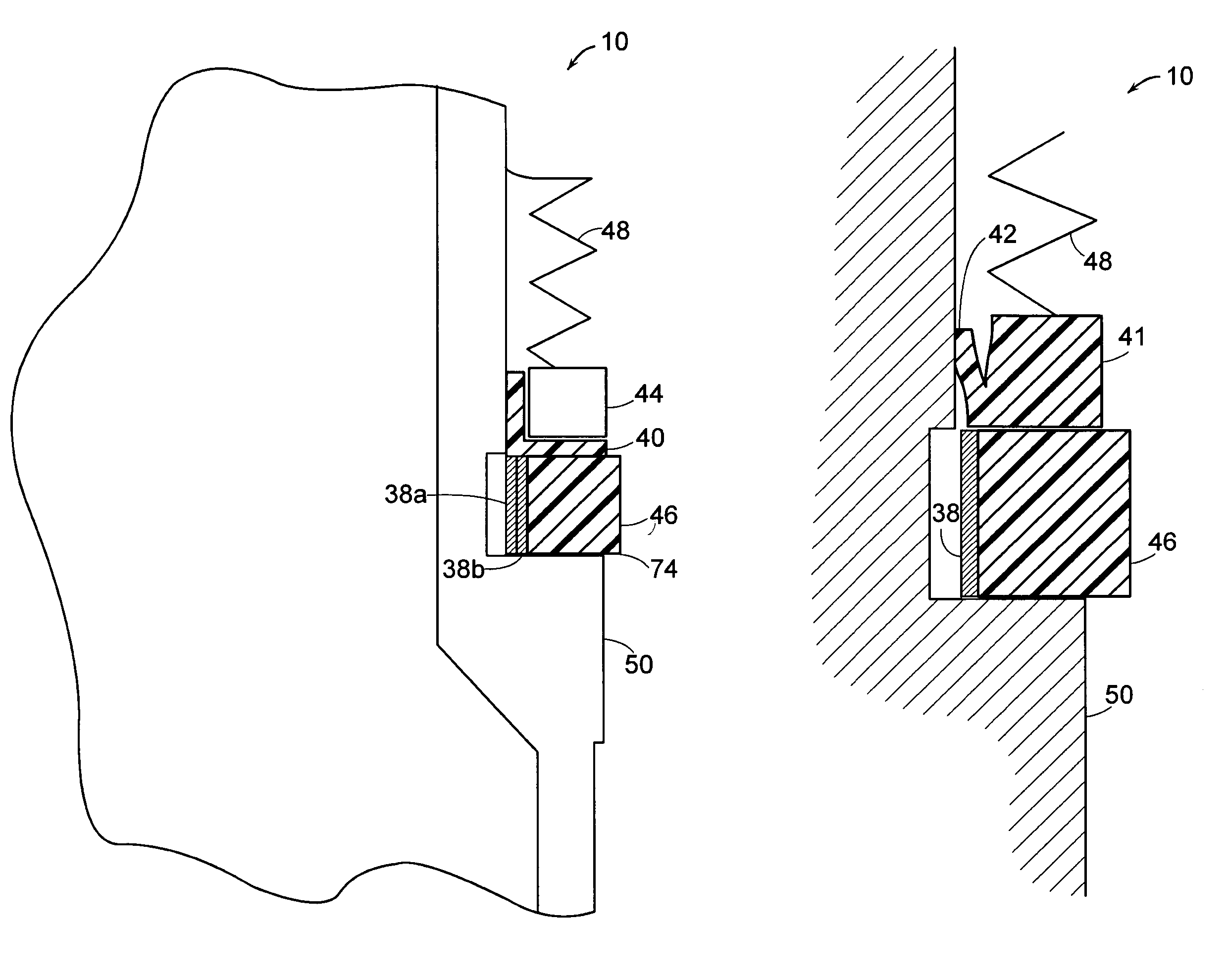
[0027]FIG. 3 illustrates a cross-sectional view of an embodiment of a piston given generally as 10. Preferably the piston 10 is a displacer, such as is used in a cryogenic refrigerator. The piston 10 includes a body 50 having a circumferential groove. The circumferential groove includes a groove wall 74 formed in the body 50. The piston 10 also includes mounted within the groove, a polymer seal ring 46, two radial springs 38a, 38b, a polymer L-ring 40, a load ring 44, and an axial biasing mechanism such as a spring 48. The design of the piston 10 allows a user to displace the spring 48 such that the spring 48 loads the seal ring 46 within a narrow load range or tolerance. Neither the load ring 44 nor the radial springs 38a, 38b are required for the practice of the invention; however each provides additional benefits in establishing a more secure seal. The load ring 44 displaces the axial load from the wave spring ...


PUM

PropertyMeasurementUnit
radial forceaaaaaaaaaa
thermal contractionaaaaaaaaaa
sealing forceaaaaaaaaaa

Abstract

A piston includes a circumferential groove having a dynamic split seal ring having a flat axially facing surface, a static seal ring having a flat axially facing surface abutting the flat surface of the dynamic seal ring, and a spring mounted within the groove. The spring exerts an axial force on the static seal ring that serves to distribute the axial load with a static seal over the dynamic split seal, thereby preventing shuttling of the split seal within the groove and restricting the leak path of the seal. Preferably, the static seal ring is a polymer and can be an L-ring, a load ring with a flange that abuts the piston body, or flanged designs. In addition, a load ring can be fitted between the L-ring and the spring. The split seal ring has at least one radial spring mounted within the seal ring to create a radial force on the split seal ring. The piston can also include a sleeve that mounts to the piston body, the sleeve forming a wall of the groove. The piston can be a displacer mounted within a cylinder of a refrigerator.

Description

BACKGROUND OF THE INVENTION[0001]In cryogenic refrigerators such as Stirling and Gifford-MacMahon type refrigerators, a piston-like displacer reciprocates within a cylinder. For efficient refrigeration in those two systems, a gas seal is provided between the displacer and cylinder to assure that refrigerant passing from one end of the displacer to the other passes through a regenerator in the displacer. One type of seal which has been widely used in such refrigerators is the split ring seal having a Z-cut there across to permit circumferential expansion of the ring without loss of sealing. The seal is positioned in a circumferential groove in the displacer and is pressed outward against the cylinder by an inner expander ring. When assembled, the split seal fits snugly within the groove. A primary advantage of such a seal in cryogenic refrigerators is that, even with wear and thermal contraction or expansion of the seal, the expander assures a fairly constant sealing force on the cyl...

Claims


Application Information

Patent Timeline
Patent Type & Authority Patents(United States)
IPC IPC(8): F25B9/00B60T11/236F02F5/00F16J9/00F16J9/06F25B9/14F16J15/16F16J15/18F16J15/20F16J15/56
CPCF16J15/164F16J15/186F16J15/56F25B9/00F16J15/20F02G2253/02Y10T29/536
Inventor SYLVIA, RUSSELL M.BARTLETT, ALLEN J.HOUSMAN, MARK E.
Owner EDWARDS VACUUM LLC
Why Eureka
Try Eureka