Grid casing for a container

Inactive Publication Date: 2006-04-11
GREIF INT HLDG BV
View PDF15 Cites 9 Cited by
  • Summary
  • Abstract
  • Description
  • Claims
  • Application Information

AI Technical Summary

Benefits of technology

[0012]When using basic grid bars having a hat-shaped profile, the ends of the bars of the additional grid bars can be expediently bent into the hat-shaped profile so that these ends of the bars do not constitute a haz

Problems solved by technology

The voluminous inner containers of pallet containers, usually manufactured of polyethylene, have a tendency to become electrostatically charged.
Inter alia, when the liquid contained in the container moves, friction on the container wall can cause electric charges which can

Method used


Image

  • Grid casing for a container
  • Grid casing for a container
  • Grid casing for a container

Examples


Embodiment Construction

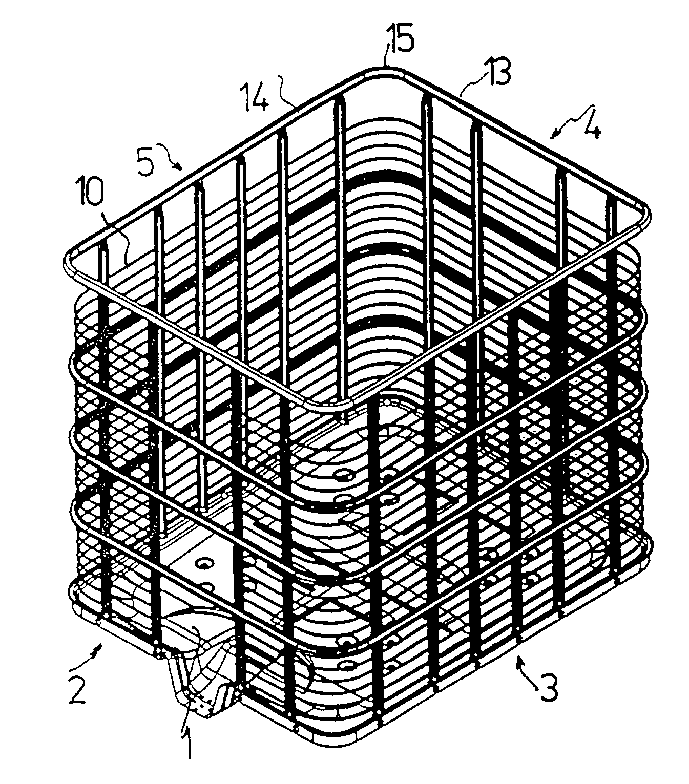
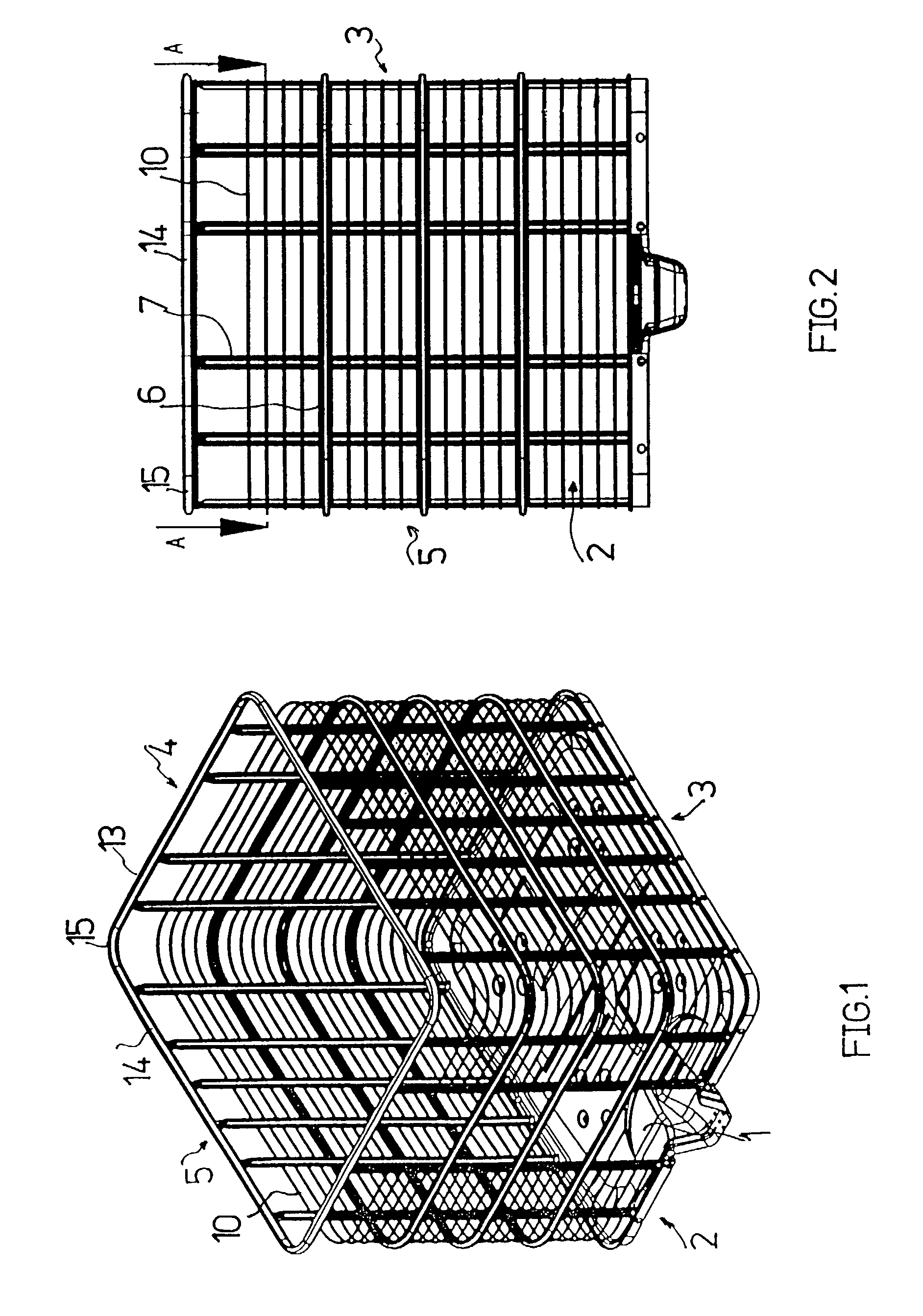
[0022]Vertical grid walls 2 to 5 extend upwardly from a sheet metal bottom 1 of a metal grid casing, wherein the walls 2 to 5 are formed by bending a grid web multiple times. The sheet metal bottom 1 is matched in regard to its shape to the inner plastic container (not illustrated) to be received in the grid casing and can be connected to a pallet (not illustrated).

[0023]The grid walls 2 to 5 comprise a basic grid of crossing basic grid bars 6 and 7 wherein the basic grid bars 6 extend horizontally and the basic grid bars 7 extend vertically.

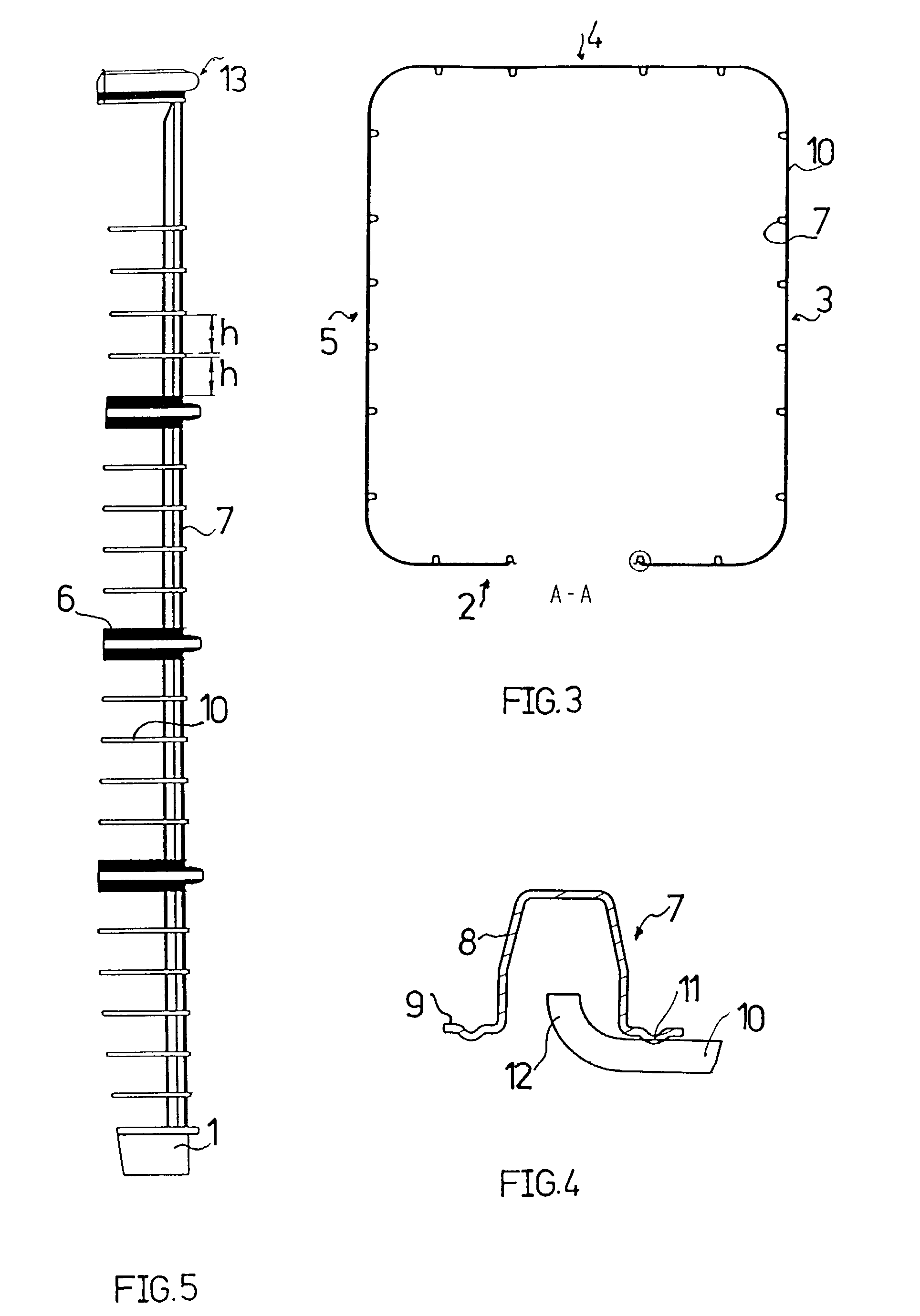
[0024]As illustrated in particular in FIG. 4, the basic grid bars of the basic grid have a hat-shaped profile 8 with rims 9.

[0025]By means of the rims 9, the crossing basic grid bars 6 and 7 are welded together at their crossing locations. The hat-shaped profile of the vertical basic grid bars 7 open toward the exterior of the grid casing while the open side of the hat-shaped profile of the horizontal basic grid bars 6 open to the interior of th...


PUM


Abstract

A grid casing for a container having a tendency to become electrostatically charged has a basic grid made of basic grid bars forming a basic grid mesh structure. The basic grid is primarily responsible for the strength of the grid casing. Additional grid bars are provided for forming a tighter grid mesh structure relative to the basic grid mesh structure of the basic grid.

Description

BACKGROUND OF THE INVENTION[0001]1. Field of the Invention[0002]The invention relates to a grid casing for a container having a tendency to become electrostatically charged, in particular, for a pallet container comprising an inner container of plastic material.[0003]2. Description of the Related Art[0004]The voluminous inner containers of pallet containers, usually manufactured of polyethylene, have a tendency to become electrostatically charged. Inter alia, when the liquid contained in the container moves, friction on the container wall can cause electric charges which cannot dissipate on the insulating material. In this way, great potential differences relative to the grid casing can result and, finally, spark discharge may occur. When employing the containers as a receptacle for flammable liquids, a fire or even explosion hazard is present.SUMMARY OF THE INVENTION[0005]It is an object of the present invention to provide a novel grid casing which eliminates the fire and explosion...

Claims


Application Information

Patent Timeline
IPC IPC(8): B65D6/08B65D77/04B65D77/06
CPCB65D77/0466B65D2213/02
Inventor HAMM, ANDRE
Owner GREIF INT HLDG BV
Why Eureka
Try Eureka