Real time calibration of a marking engine in a print system

a marking engine and print system technology, applied in the field ofelectrophotographic printers, can solve the problems of lag time, extremely inaccurate determination of low toner level in cartridges, etc., and achieve the effect of significant time savings and greater productivity

Inactive Publication Date: 2006-04-11
ELECTRONICS FOR IMAGING
View PDF49 Cites 59 Cited by
  • Summary
  • Abstract
  • Description
  • Claims
  • Application Information

AI Technical Summary

Benefits of technology

[0014]According to the present disclosure, significant time savings and greater productivity can be realized if the operator is able to make adjustments during the print time, i.e., while the print job is in progress. What is desired is a method that allows one or more marking engines to be adjusted with respect to such parameters as gray balance, linearity, density level, hue, saturation, lightness, brightness, or contrast without interrupting, stopping or pulling the marking engine or engines from a running print job. Disclosed herein is a method for modifying the rendered output of the marking engine for a print job in progress. The method comprises th

Problems solved by technology

However, in a multipass color process, multiple images must be superimposed on one another on the sheet of paper in a direct transfer system, thus requiring multiple passes of the paper or image carrier through the print engine.
When dealing with multiple print engines, there can be a problem that exists wi

Method used


Image

  • Real time calibration of a marking engine in a print system
  • Real time calibration of a marking engine in a print system
  • Real time calibration of a marking engine in a print system

Examples


Embodiment Construction

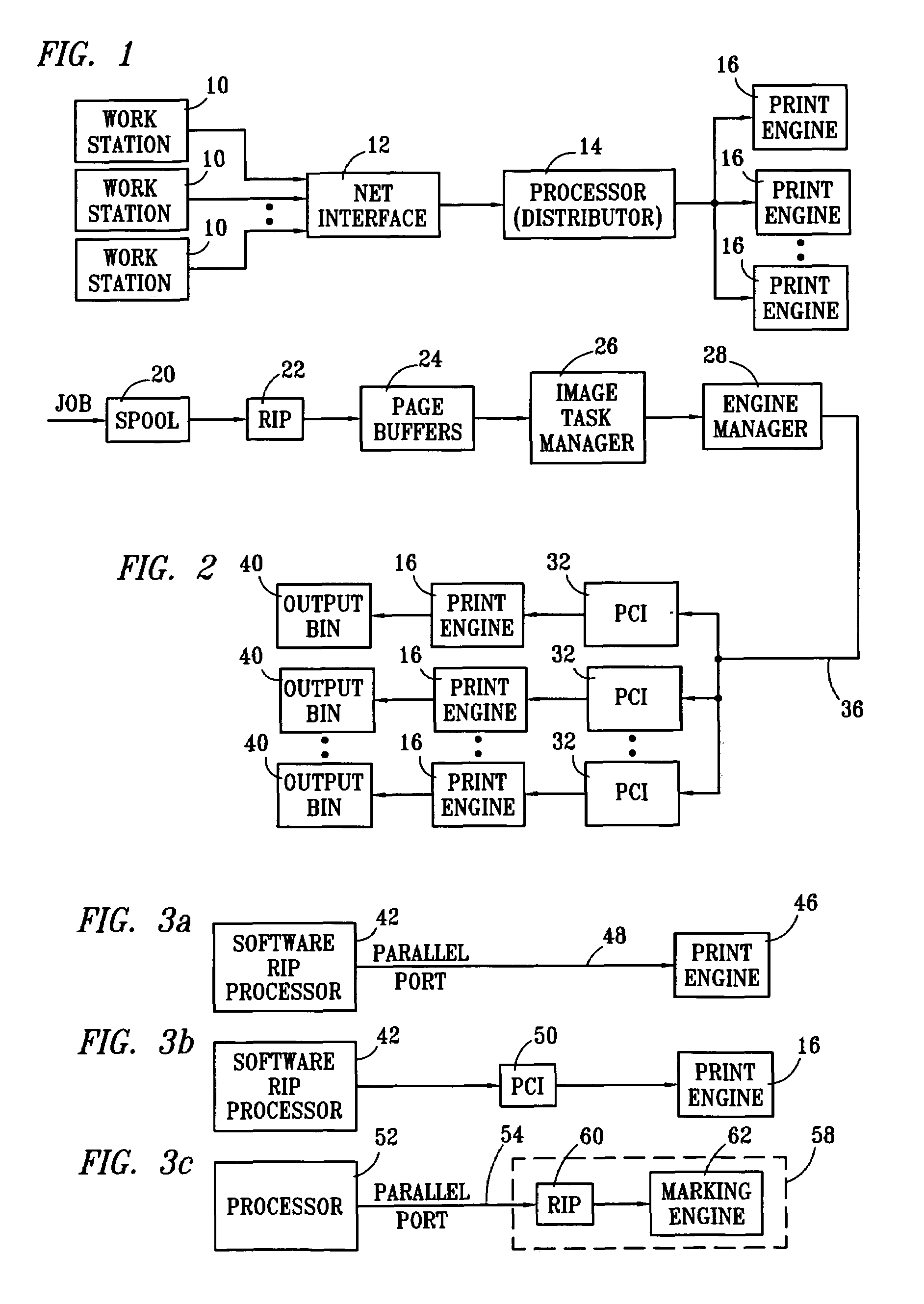
[0071]Referring now to FIG. 1, there is illustrated a block diagram of the overall operation of the virtual printing system. A plurality of workstations 10 are provided, which workstations 10 comprise general personal computers or other terminals that allow a user to create print jobs. Each of the workstations is networked through a network interface 12, which is a conventional type of general network interface such as an Ethernet® network interface. This allows each workstation 10 to send its print job to a central processor 14, which processor is operable to process the print jobs in accordance with the system of the present invention and distribute these print jobs to multiple print engines 16. As will be described hereinbelow, the processor 14 is operable to disassemble the print job, parse the print job into different pages and distribute the parsed pages in a predetermined manner in accordance with the present invention. It should be understood that a print job, although initi...


PUM


Abstract

A method for modifying the rendered output of a marking engine for a print job in progress is disclosed, comprising the steps of comparing a sample rendered input image having included therewith a print target scale corresponding to a specified image parameter having a range of possible renderings set forth in a table, with a rendering included in the table and modifying, to match a desired rendering, numerical correction data in one or more look-up tables of a print adapter, which print adapter is coupled to a source of input image data for the print job in progress and having an output coupled to the marking engine. The modified input image data is transmitted to the marking engine for rendering the remainder of the print job.

Description

CROSS-REFERENCE TO RELATED APPLICATIONS[0001]This application is a Continuation-in-Part of U.S. patent application Ser. No. 09 / 229,244, filed Jan. 12, 1999, now U.S. Pat. No. 6,219,155 issued Apr. 17, 2001 and entitled “COLOR CORRECTION OF CONTONE IMAGES IN A MULTIPLE PRINT ENGINE SYSTEM,”which is a divisional application of Ser. No. 08 / 788,133, filed on Jan. 23, 1997, now U.S. Pat. No. 6,035,103 issued Mar. 7, 2000 and entitled “COLOR CORRECTION FOR MULTIPLE PRINT ENGINE SYSTEM WITH HALF TONE AND BI-LEVEL PRINTING,” which is a Continuation-in-Part of Ser. No. 08 / 698,999, filed Aug. 16, 1996 now U.S. Pat. No. 5,859,711 issued Jan. 12, 1999 and entitled “Multiple Print Engine with Virtual Job Routing”, which is a Continuation-in-Part of U.S. patent application Ser. No. 08 / 511,641, filed Aug. 7, 1995, now U.S. Pat. No. 6,657,741 entitled “Virtual Single Print Engine with Software Rip” and is related to U.S. Pat. No. 5,596,416 issued Jan. 21, 1997 and entitled “Multiple Printer Module ...

Claims


Application Information

Patent Timeline
IPC IPC(8): H04N1/407H04N1/60
CPCH04N1/00002H04N1/00015H04N1/00031H04N1/6033H04N1/00053H04N1/00063H04N1/00087H04N1/00045
Inventor ZUBER, PETER A.
Owner ELECTRONICS FOR IMAGING
Why Eureka
Try Eureka