
Data erasing apparatus

a technology for erasing apparatuses and data, applied in the field of data erasing apparatuses, can solve the problems of ease of use, difficult to insert and remove magnetic disk drives, and apparatuses that are not suitable for erasing data for preventing

Inactive Publication Date: 2006-04-11
KK TOSHIBA
View PDF8 Cites 15 Cited by
  • Summary
  • Abstract
  • Description
  • Claims
  • Application Information

AI Technical Summary

Benefits of technology

The present invention provides a data erasing apparatus that is designed to remove data from a magnetic disk drive when scrapping or recycling it. The apparatus includes a magnetic field generating means and a moving mechanism that moves the drive in and out of the magnetic field. The technical effect of this invention is that it provides an efficient and easy-to-use tool for erasing data from magnetic disk drives.

Problems solved by technology

However, this apparatus is not suited as a data erasure apparatus for preventing data leakage when scrapping or recycling the magnetic disk, because it requires the step of exposing the magnetic disk outside the drive for data erasure, and because there is the possibility that the magnetic disk may not rotate due to failure.
To erase data on a magnetic disk with the magnetic disk enclosed within a metal housing, an even stronger magnetic field is required, but it is difficult to insert and remove the magnetic disk drive by overcoming the attraction force working in such a strong magnetic field.
However, this presents a problem in terms of ease of use, because the power supply for energizing the coils is always required, and because the operation for turning on and off the power supply has to be performed each time.

Method used


Image

  • Data erasing apparatus
  • Data erasing apparatus
  • Data erasing apparatus

Examples


first embodiment

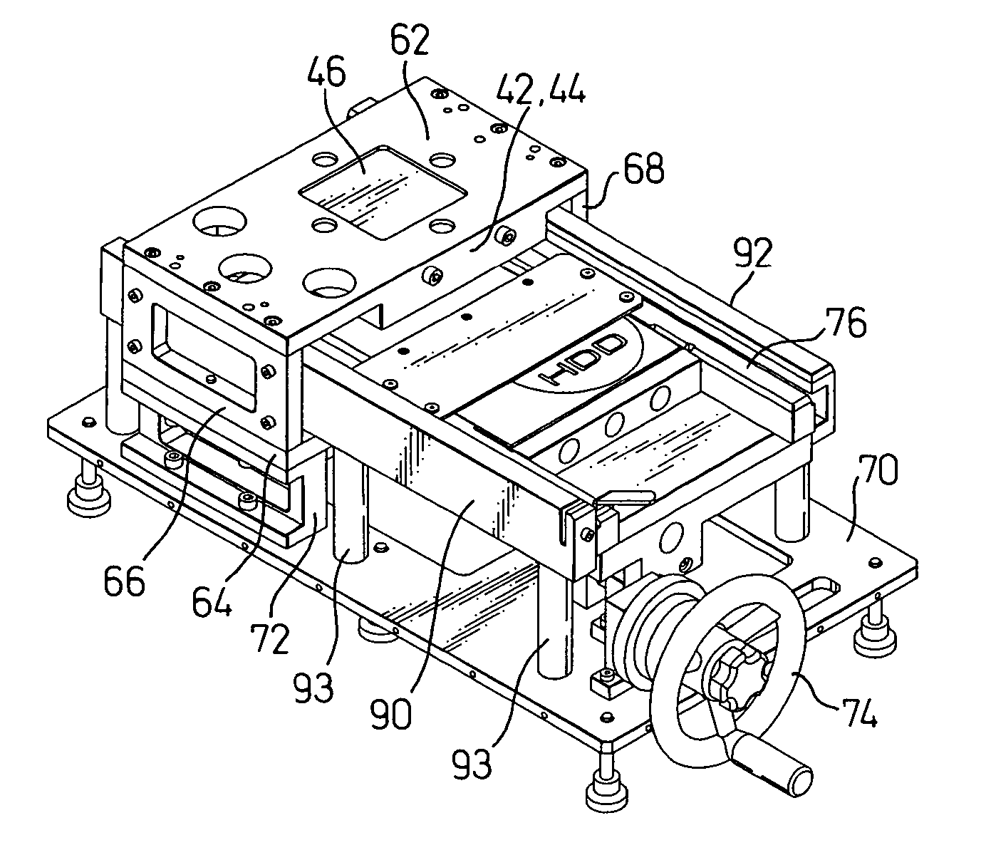
[0040]FIG. 4 is a perspective view of a data erasing apparatus 60 according to the present invention, and FIG. 5 is a diagram for explaining the internal construction of the data erasing apparatus 60 with a cover 61 removed from it.

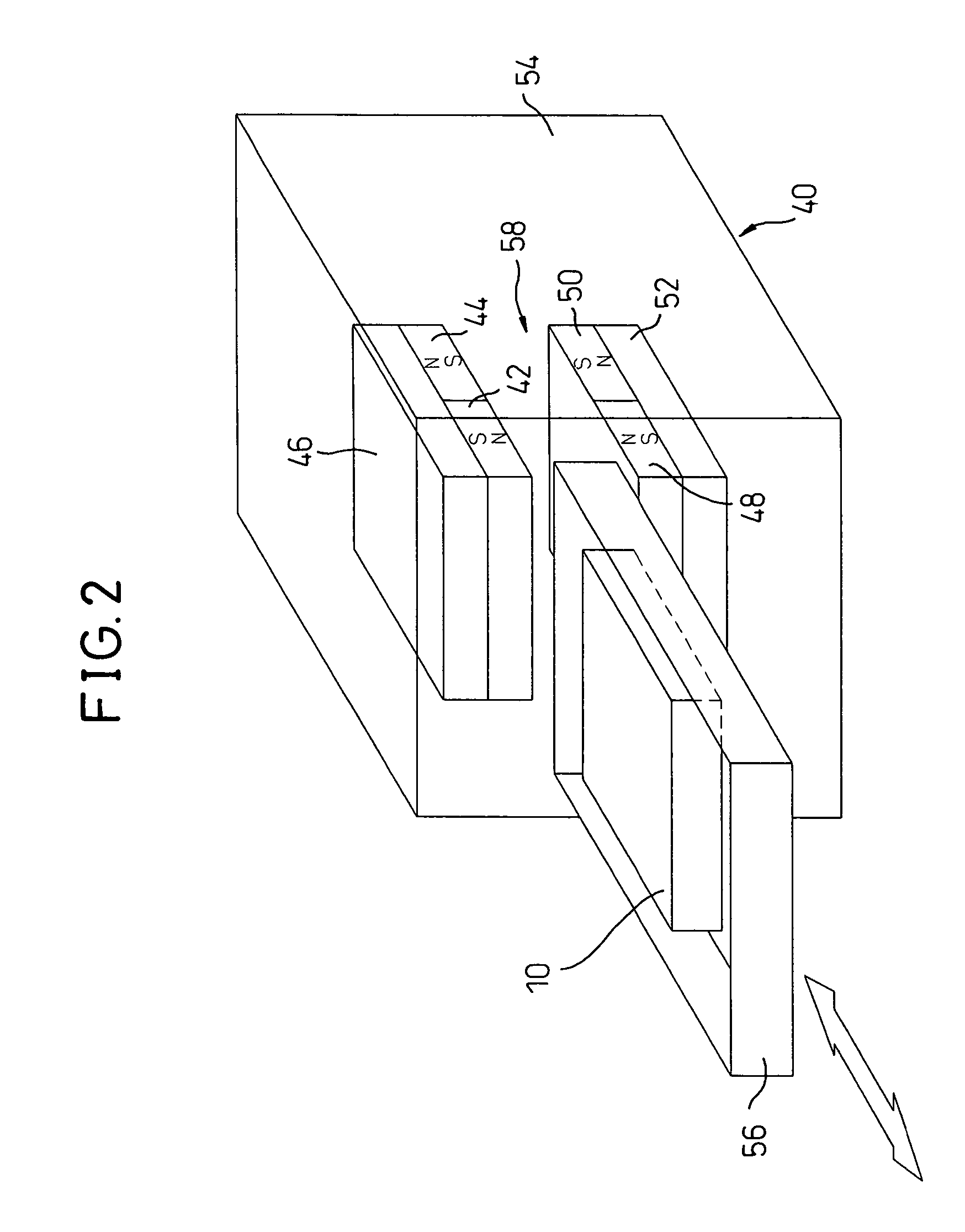
[0041]As shown in FIG. 5, the permanent magnets 42 and 44 and the yoke 46 are mounted to an upper frame 62, and the permanent magnets 48 and 50 (not shown) and the yoke 52 (not shown) are mounted to a lower frame 64. The upper frame 62 and the lower frame 64 and mounted to side frames 66 and 68, and the entire assembly is secured to a stand 72 mounted on a base 70.

[0042]If the magnetic flux from the magnets heavily leaks outside the cover 61, ill effects may be caused, for example, to precision instruments, causing them to malfunction. Therefore, shield plates 73 may be provided on the frames 62, 66, and 68, as shown in FIG. 6, to reduce the magnetic flux leaking outside. For the shield plates 73, a material such as iron, silicon steel, or permalloy is us...

second embodiment

[0052]FIG. 13 is a perspective view of a data erasing apparatus 100 according to the present invention, and FIG. 14 is a diagram for explaining the internal construction of the data erasing apparatus 100 with a cover 102 removed from it.

[0053]The same component elements as those of the data erasing apparatus 60 described with reference to FIGS. 4 to 12 will be designated by the same reference numerals, and the description thereof will not be repeated here. The difference from the data erasing apparatus 60 is that the HDD holder 76 is moved into and out of the space between the upper magnet block and the lower magnet block by means of a ballscrew 106 connected to an electric motor 104. The assembly consisting of the upper and lower frames 62 and 64 and side frames 66 and 68 is mounted directly on the base 70. Further, shield plates 73 may be provided on the frames 62, 66, and 68, as shown in FIG. 15, to reduce the magnetic flux leaking outside.

[0054]FIG. 16 is a diagram for explainin...


PUM

PropertyMeasurementUnit
magnetic fieldaaaaaaaaaa
rotational forceaaaaaaaaaa
magneticaaaaaaaaaa

Abstract

The invention enables a magnetic disk drive to be inserted and removed against an attraction force exerted by a magnetic force that is strong enough to erase data on a magnetic disk enclosed within a metal case. A converting mechanism comprising a ballscrew and a ballscrew nut bracket is provided that converts rotational motion of a handle into translational motion of an HDD holder; by rotating the handle, the HDD holder with the hard disk drive mounted thereon is moved in the inserting and removing directions by overcoming the attraction force being exerted by the magnetic field generated by means of a permanent magnet. An electric motor may be used to generate the rotational force.

Description

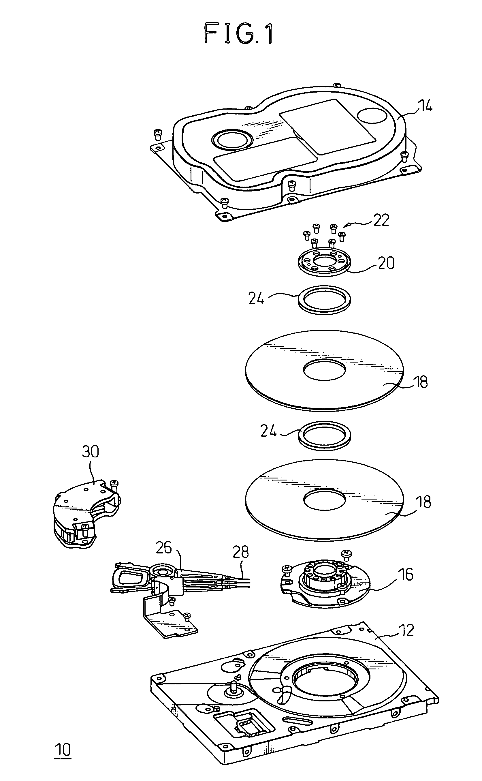
BACKGROUND OF THE INVENTION[0001]1. Field of the Invention[0002]The present invention relates to a data erasing apparatus for erasing data recorded on a magnetic disk(s) contained in a magnetic disk drive in order to prevent the risk of data leakage, etc. when scrapping or recycling the magnetic disk drive.[0003]2. Description of the Related Art[0004]To recycle non-defective magnetic disks used in magnetic disk drives rendered defective in the manufacturing process of magnetic disk drives, Japanese Unexamined Patent Publication No. 2001-331904 discloses a data erasing apparatus for erasing servo data written on a magnetic disk; this data erasing apparatus accomplishes data erasure by applying a magnetic field to the magnetic disk, with a portion thereof inserted between permanent magnets, while rotating the magnetic disk by driving the spindle motor in the disk drive. However, this apparatus is not suited as a data erasure apparatus for preventing data leakage when scrapping or recy...

Claims


Application Information

Patent Timeline
Patent Type & Authority Patents(United States)
IPC IPC(8): G11B5/03G11B5/024G11B23/50G11B25/04
CPCG11B5/0245G11B25/043G11B23/505
Inventor HASEGAWA, HIROSHISUZUKI, HISATOSUZUKI, KAZUTOSHIUEMATSU, HIROYUKIONO, TAKAHIRO
Owner KK TOSHIBA
Learn More