Compact electronics plenum

a compact, electronic technology, applied in the direction of cooling/ventilation/heating modification, semiconductor/solid-state device details, semiconductor devices, etc., can solve the problems of difficult to effectively cool some of these smaller device packages, and still generate a significant amount of hea

Inactive Publication Date: 2006-04-11
IGO INC
View PDF11 Cites 72 Cited by
  • Summary
  • Abstract
  • Description
  • Claims
  • Application Information

AI Technical Summary

Benefits of technology

[0004]The present invention achieves technical advantages as a compact cooling system including a plenum formed of a thermally conductive material, the plenum including both a plurality of passageways adapted to pass air therethrough, and also having an integral receptacle adapted to wick heat from a heat generating component and transfer the heat to the passageways.
[0006]Advantageously, heat is efficiently transferred from the heat generating component to the plenum, and the plenum is efficiently cooled flowing air created the fan so as to provide an extremely compact design.
[0007]In one preferred embodiment of the present invention, the base has an upper surface and a lower surface, whereby the fins extend outwardly from the upper surface, and the receptacle extends outwardly from the lower surface. The base, fins and receptacle are formed as a unitary plenum, and the fins may be formed generally parallel to one another to define the plurality of adjacent passageways. A thermally conductive lid may be coupled to the plenum to define the passageways, whereby the fins separate one passageway from another. The fins are preferably formed as a plurality of generally collinear fins in a plurality of rows. The fins of each row are separated from one another and form a brush-like arrangement so that air passing thereacross, and therebetween, can efficiency transfer heat therefrom to provide maximum cooling efficiency.
[0008]In one embodiment of the present invention, the base may also include a plurality of openings extending therethrough and communicating with the passageways. These openings are adapted to generate a venturi effect when air is communicated thereacross and through the passageways, thereby drawing heat from inside a package, through the openings, and into the passageways for dispersing thereof.

Problems solved by technology

While the miniaturization of components facilitates the overall reduction in device package size, a significant amount of heat is still generated by these components.
It is increasingly difficult to effectively cool some of these smaller device packages as the heat generated per unit area is increasing.

Method used


Image

  • Compact electronics plenum
  • Compact electronics plenum
  • Compact electronics plenum

Examples


Embodiment Construction

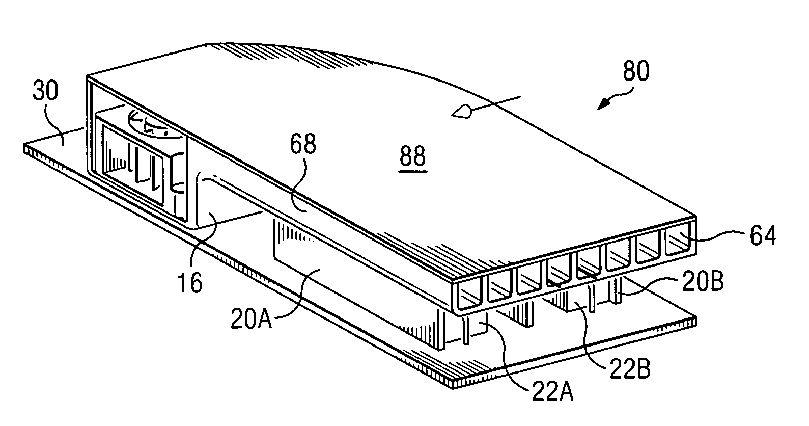
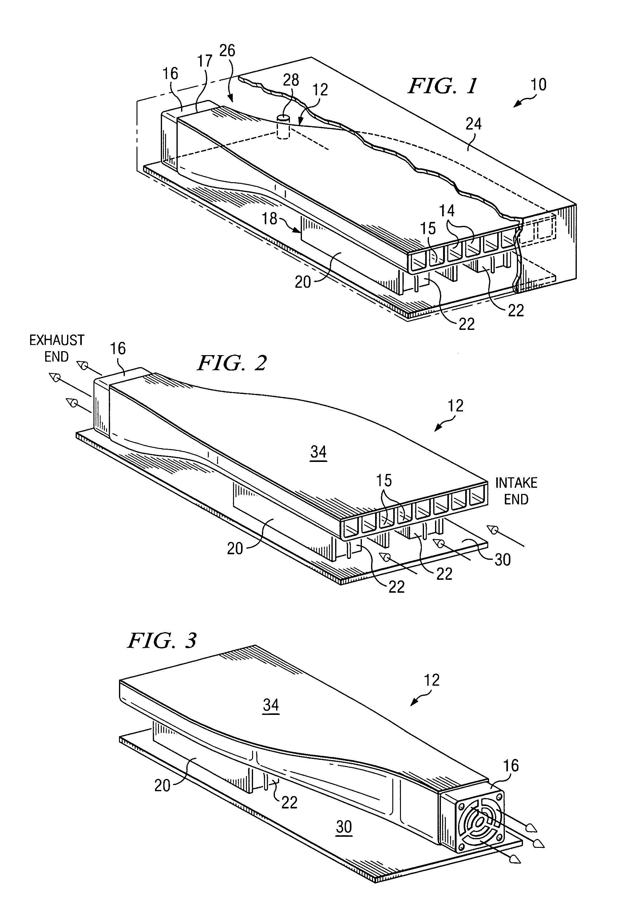
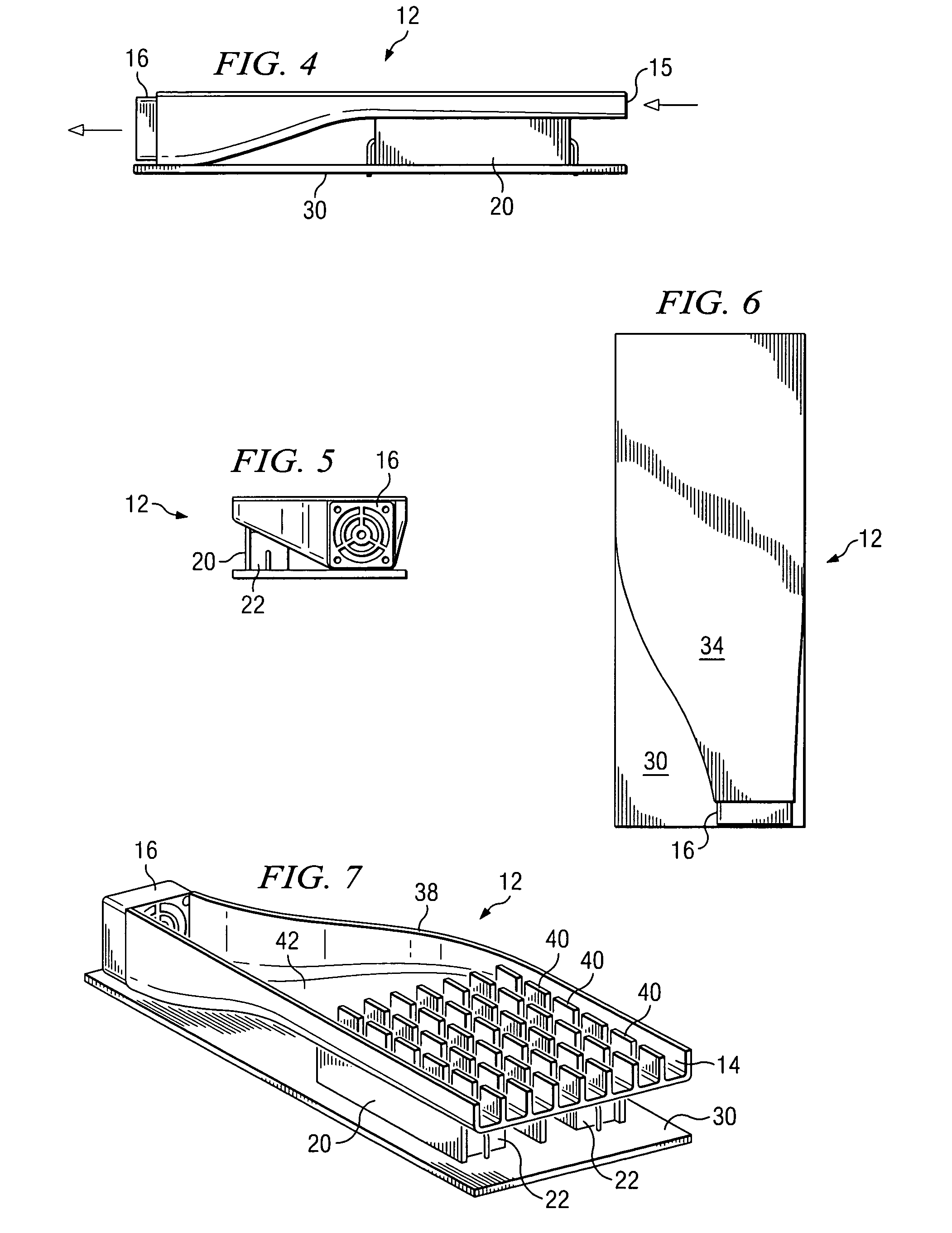
[0030]Referring now to FIG. 1, there is generally illustrated at 10 a power converter device thermally coupled to a plenum 12 according to a first preferred embodiment of the present invention. Plenum 12 is seen to have a plurality of passageways 14 each having an intake opening 15, and an opposing fan 16 at a exhaust opening 17 and thereof. Plenum 12 is also seen to include a plurality of receptacles 18 formed by integral downwardly extending members 20, each receptacle 18 seen to frictionally receive a respective heat generating electrical component 22. Plenum 12 is advantageously configured to wick heat from the heat generating members 22, and then transfer this heat to surface areas in contact with passageways 14 such that the flow of air therethrough removes heat therefrom. Device 10 is further seen to include a package housing 24 defining a chamber 26 therein housing other electrical component 28 forming a portion of the power converter housed therein.

[0031]Referring to FIG. 2...


PUM


Abstract

A plenum (12, 60) having a plurality of heat fins (40, 72) and also a receptacle (20) for receiving a heat generating component (22) in a friction fit arrangement. The plenum has a plurality of passageways (14, 66) defined by the plurality of fins arranged in rows, and also includes a plurality of openings (50, 76) disposed between the fin. The receptacle frictionally receives a respective heat generating component (22), and wicks heat to the fins. Air communicating through the passageways defined by the fins removes heat from the fins, and also creates a venturi effect to remove heat from within a housing via the openings to further cool the portable electronic device.

Description

FIELD OF THE INVENTION[0001]The present invention is generally related to heat cooling systems for portable electronic devices, and more particularly to a heat cooling system including a plenum to remove heat from ultra-compact devices including power converters, transmitters, amplifiers, and so forth.BACKGROUND OF THE INVENTION[0002]The miniaturization of portable consumer electronic devices is being revolutionalized by the dramatic miniaturization of electrical components, and the improved efficiencies of these electrical components. Exemplary miniaturized portable consumer electronics include power converter devices, transmitters, amplifiers, cell phones, PDA's, MP3 players, just to name a few, are made possible by improvements in technology.[0003]While the miniaturization of components facilitates the overall reduction in device package size, a significant amount of heat is still generated by these components. It is increasingly difficult to effectively cool some of these smalle...

Claims


Application Information

Patent Timeline
Patent Type & Authority Patents(United States)
IPC IPC(8): H05K7/20
CPCH01L23/467H01L2924/0002H01L2924/00F28F3/048
Inventor LORD, CHARLES
Owner IGO INC
Why Eureka
Try Eureka