Delay optimization designing system and delay optimization designing method for a logic circuit and control program

a design method and logic circuit technology, applied in pulse generators, pulse techniques, instruments, etc., can solve the problems of insufficient delay optimization, inability of the person to take a suitable countermeasure, and inability to reduce the delay of the overall logic circui

Inactive Publication Date: 2006-04-11
NEC CORP
View PDF7 Cites 8 Cited by
  • Summary
  • Abstract
  • Description
  • Claims
  • Application Information

AI Technical Summary

Benefits of technology

[0012]It is an object of the present invention to provide a delay optimization designing system and a delay optimization designing method for a logic circuit and a control program by which reduction of the delay of an output and ...

Problems solved by technology

It is a first problem that, since the position of a flip-flop changes, operation of the flip-flop which makes a base of a logic analysis is different between an initial logic circuit and a logic circuit after optimization.
Therefore, there is a drawback that, if a person who has designed the initial logic circuit...

Method used


Image

  • Delay optimization designing system and delay optimization designing method for a logic circuit and control program
  • Delay optimization designing system and delay optimization designing method for a logic circuit and control program
  • Delay optimization designing system and delay optimization designing method for a logic circuit and control program

Examples


Embodiment Construction

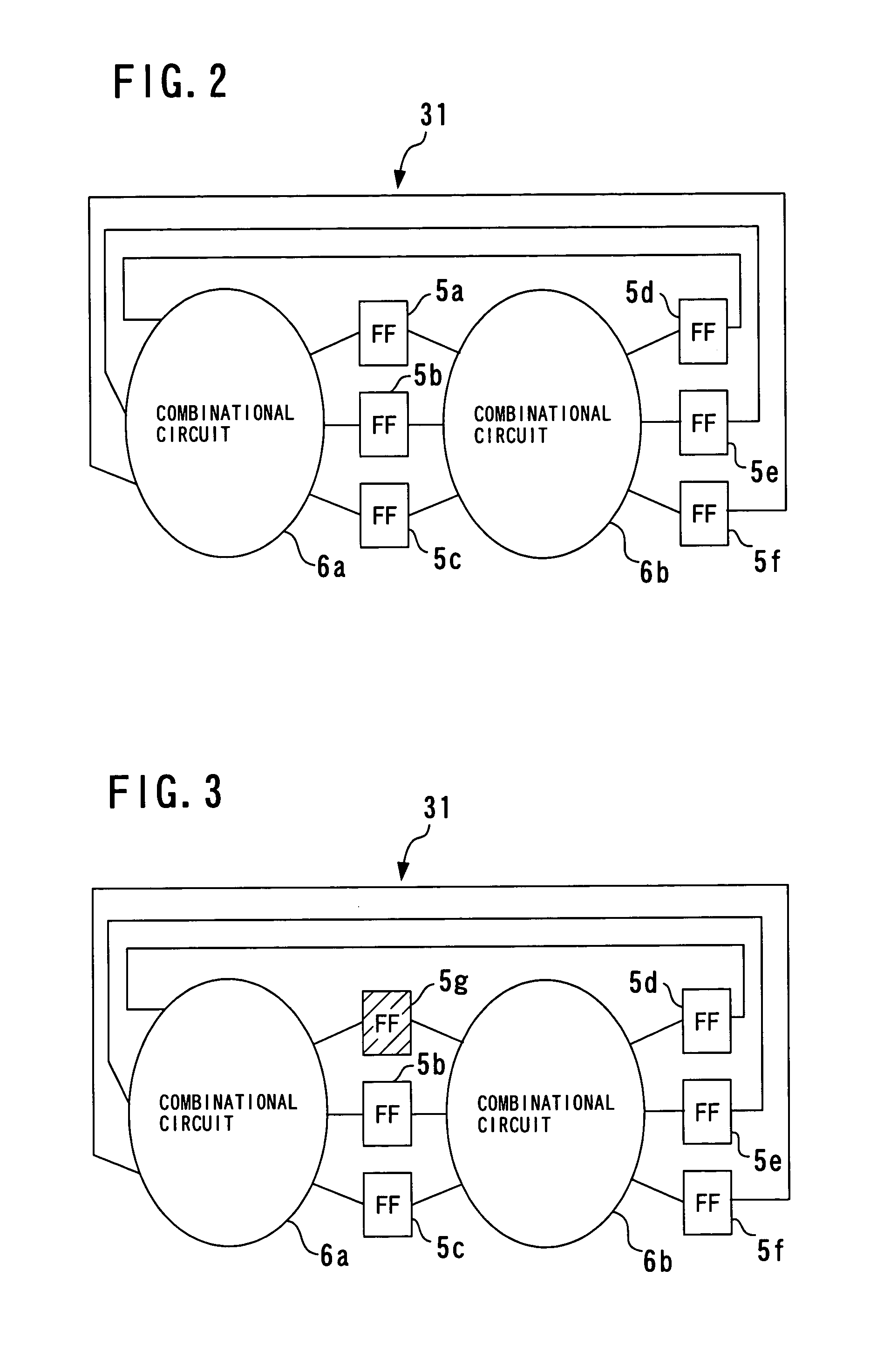
[0035]Referring first to FIG. 2, there is shown an example of a logic circuit which is to make an object of optimization. The logic circuit shown is formed from a sequential circuit including flip-flops (FF) 5a to 5f and combinational circuits 6a and 6b formed from logic circuit devices. FIG. 3 illustrates a state of the sequential circuit after non-latch substitution designation is performed for the logic circuit just described, and particularly illustrates, as an example, a state after the non-latch substitution designation is performed for the flip-flop (FF) 5g. FIG. 4 illustrates a state of the sequential circuit after latch substitution, and particularly shows, as an example, a state after the flip-flops (FF) 5b to 5f are substituted into low-active latches (LL) 7a to 7e, respectively. FIG. 5 illustrates, as an example, a state after high-active latches (HL) 8a to 8d are inserted into the sequential circuit shown in FIG. 4.

[0036]Here, a flip-flop (FF), a low-active latch (LL) a...


PUM


Abstract

A delay optimization designing system and method is disclosed by which reduction of outputting delay and setup time of flip-flops and clock skew can be achieved and sufficient delay optimization can be achieved. A delay optimization designing system for a logic circuit includes a flip-flop selection section for selecting any flip-flop not to be substituted into a latch from within a given logic circuit, a flip-flop searching section for searching any flip-flop having a delay margin from among the flip-flops which are not selected by the flip-flop selection section, and a latch substitution section for substituting any flip-flop searched by the flip-flop searching section into a latch which passes a signal to the output side therethrough faster than the searched flip-flop.

Description

BACKGROUND OF THE INVENTION[0001]1. Field of the Invention[0002]The present invention relates to a delay optimization designing system and a delay optimization designing method for a logic circuit and a control program, and more particularly to a delay optimization designing system and a delay optimization designing method for a sequential circuit and a control program.[0003]2. Description of the Related Art[0004]For delay optimization of a logic circuit, two methods are available including a delay optimization method for a sequential circuit which performs optimization regarding flip-flops and / or latches and another delay optimization method for a portion of a combinational circuit which exists between a flip-flop and a latch, between flip-flops and / or between latches. The present invention specifically relates to a method of delay optimization for a sequential circuit.[0005]Conventionally, for delay optimization of a sequential circuit, a method called “retiming” is available and ...

Claims


Application Information

Patent Timeline
IPC IPC(8): G06F17/50H03K3/037
CPCG06F17/5045G06F30/30
Inventor KANAMARU, KEISUKEYOSHIKAWA, KO
Owner NEC CORP
Why Eureka
Try Eureka