Method of shot blasting and a machine for implementing such a method

Inactive Publication Date: 2006-04-18
SN DETUDE & DE CONSTR DE MOTEURS DAVIATION S N E C M A
View PDF27 Cites 26 Cited by
  • Summary
  • Abstract
  • Description
  • Claims
  • Application Information

AI Technical Summary

Benefits of technology

[0046]It is possible to take advantage of the shot peening to mark the part by interposing a mask between a face of the part and the projectiles, the mask having apertures that co

Problems solved by technology

If a part is not sufficiently shot peened, then it is not given the desired fatigue resistance, whereas if it is excessively shot peened, then the part suffers irreversible damage and its resistance diminishes, and

Method used


Image

  • Method of shot blasting and a machine for implementing such a method
  • Method of shot blasting and a machine for implementing such a method
  • Method of shot blasting and a machine for implementing such a method

Examples


Embodiment Construction

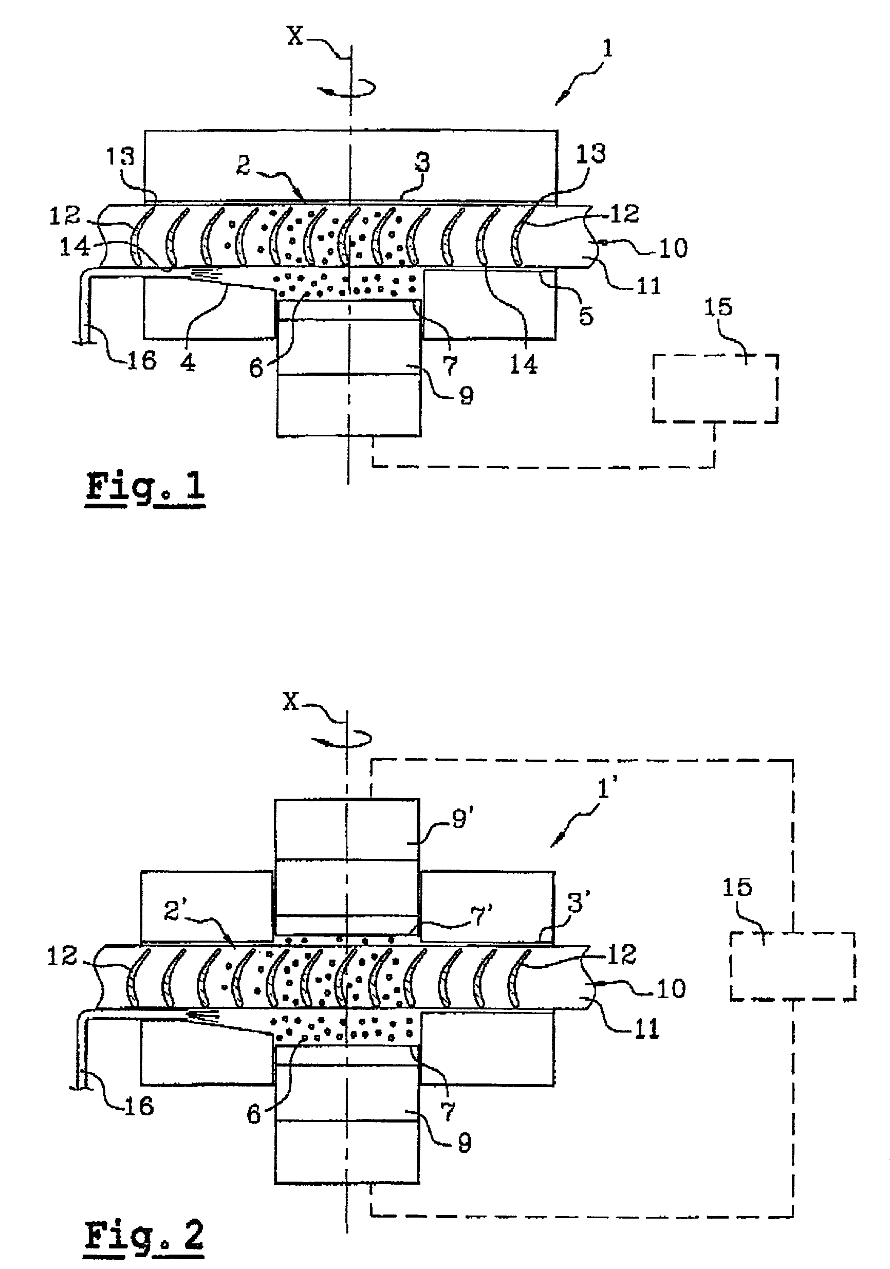
[0076]FIG. 1 shows a first embodiment of shot peening apparatus 1 enabling the method of the invention to be implemented.

[0077]This apparatus 1 comprises a treatment chamber 2 formed between a top wall 3 and bottom walls 4 and 5, in which chamber a cloud of projectiles 6 is generated by means of a vibrating surface 7 which in this case corresponds to the top end of a sonotrode 9.

[0078]The wall 5 is situated upstream from the treatment chamber 2 while the wall 4 is situated downstream.

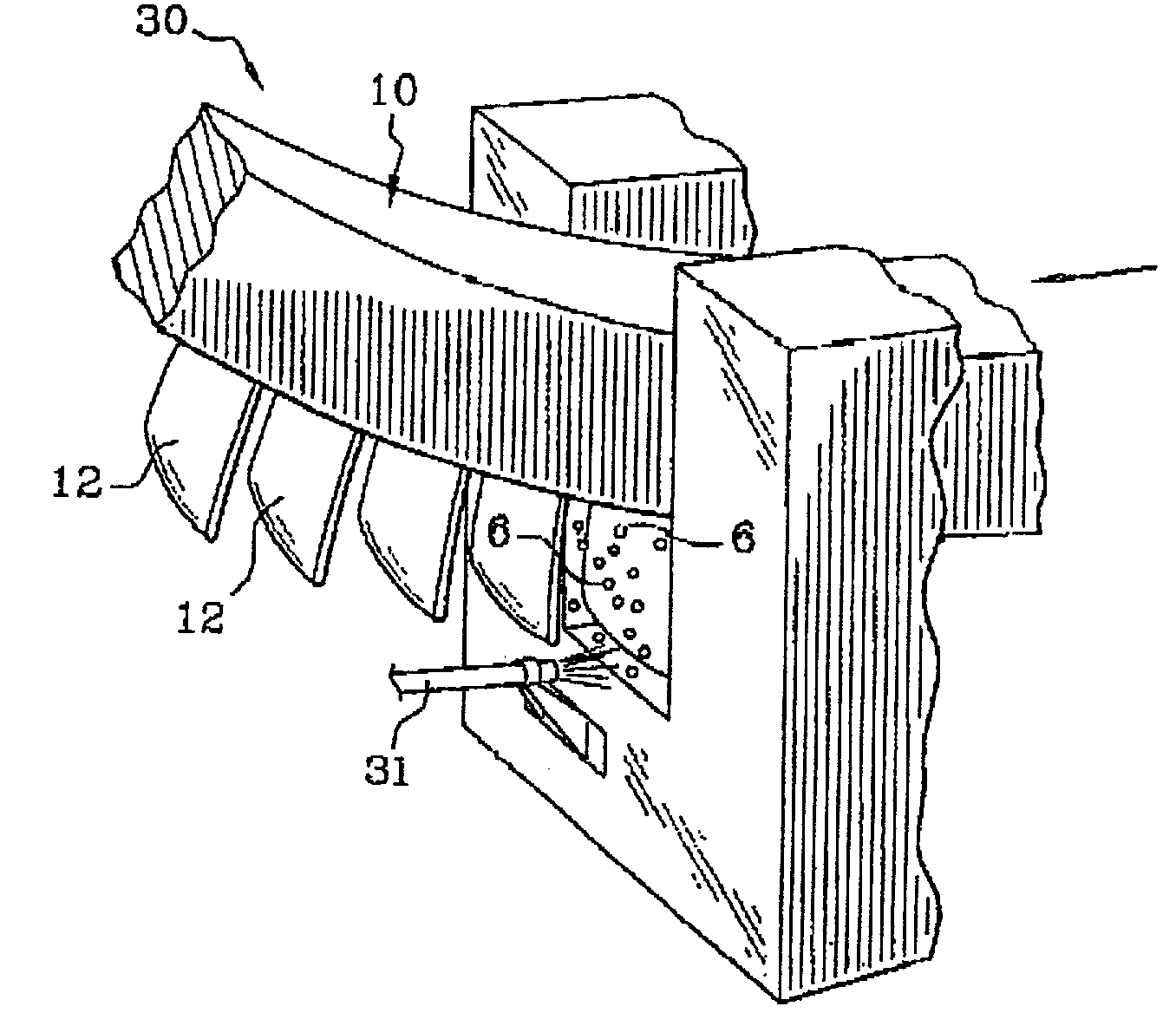
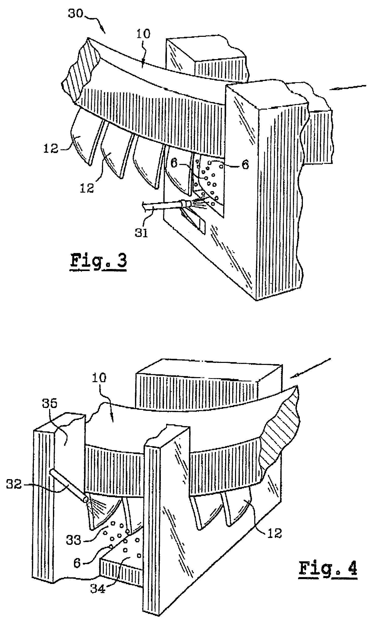
[0079]The part to be treated is constituted in this case by a vaned wheel 10 rotated about a vertical axis X, the wheel comprising a generally annular support 11 provided on its outer periphery with blades 12, e.g. blades that are formed integrally with the support 11.

[0080]It would not go beyond the ambit of the present invention for the blades to be made separately and assembled on the support prior to treatment.

[0081]The blades 12 are relatively thin compared with their height, as measured in the dir...


PUM

PropertyMeasurementUnit
Fractionaaaaaaaaaa
Timeaaaaaaaaaa
Areaaaaaaaaaaa

Abstract

A part to be shot peened includes at least one thin wall (12″) defining two opposite main faces, the square root of the area of each face being greater than the mean distance between the two faces by a factor of at least five, and preferably by a factor of at least ten. According to the method, the part is caused to rotate at least intermittently relative to one or more vibrating surfaces, with at least one of the main faces being exposed to projectiles (6) set into motion by one or more of the vibrating surfaces, treatment taking place progressively on the face(s) so as to impart compression stresses thereto, with a portion only of the part being treated at any one time and with regions of the part preferably being exposed on several occasions to the projectiles, with relative rotation taking place between the exposures.

Description

[0001]This application claims the benefit of U.S. Provisional Patent Application No. 60 / 246,095, filed Nov. 7, 2000.BACKGROUND OF THE INVENTION[0002]1. Field of Invention[0003]The present invention relates to a method of shot peening metal parts, and also to a machine enabling such a method to be implemented.[0004]2. Discussion of Related Art[0005]The technique of shot peening metal parts is well known and consists in imparting compression stresses to the surface of the part by subjecting it to bombardment from projectiles constituted by balls or small shot.[0006]The permanent stress induced on the part by such bombardment has the effect of opposing the appearance and the propagation of cracks, thereby improving the fatigue resistance of the treated part.[0007]It is known that a part can be shot peened by projecting the projectiles towards the surface for treatment by means of a nozzle that is fed with compressed gas.[0008]That technique poses at least two problems when applied to t...

Claims


Application Information

Patent Timeline
IPC IPC(8): B21C37/30B21K25/00B24B1/04B24B39/00B24C1/10B24C5/08F01D5/28F01D25/00
CPCB24B1/04B24B39/006B24C1/10B24C5/005B24C5/08F01D25/002F01D5/286Y10T29/49316F05D2200/211Y10T29/49321Y10T29/479
Inventor CHEPPE, PATRICKDUCHAZEAUBENEIX, JEAN-MICHEL
Owner SN DETUDE & DE CONSTR DE MOTEURS DAVIATION S N E C M A
Why Eureka
Try Eureka