Fuel supply system for an internal combustion engine

a fuel supply system and internal combustion engine technology, applied in the direction of liquid fuel feeders, combustion air/fuel air treatment, machines/engines, etc., can solve the problems of omission of catalytic converters, rapid ageing, and reduction of noble metal content needed in exhaust gas catalytic converters, so as to reduce exhaust gas emissions and noble metal content

Inactive Publication Date: 2006-04-18
DAIMLER AG
View PDF12 Cites 35 Cited by
  • Summary
  • Abstract
  • Description
  • Claims
  • Application Information

AI Technical Summary

Benefits of technology

[0008]With this arrangement excess fuel can be fed back into the respective storage container, separated in accordance with main fuel and starting fuel. As a further advantage, in this way it is possible for starting fuel once obtained to be saved, in order to have it available in the shortest possible time, for example for reducing the exhaust gas emissions in cold-start situations. As a result of the considerable reduction in the pollutant emission, in particular in the emission of hydrocarbons, this results firstly in a reduction in the noble metal content needed in the exhaust gas catalytic converters, secondly the omission of the catalytic converters close to the engine, which, because of the high temperatures in this region, would be subjected to rapid ageing.

Problems solved by technology

As a result of the considerable reduction in the pollutant emission, in particular in the emission of hydrocarbons, this results firstly in a reduction in the noble metal content needed in the exhaust gas catalytic converters, secondly the omission of the catalytic converters close to the engine, which, because of the high temperatures in this region, would be subjected to rapid ageing.

Method used


Image

  • Fuel supply system for an internal combustion engine
  • Fuel supply system for an internal combustion engine
  • Fuel supply system for an internal combustion engine

Examples


Embodiment Construction

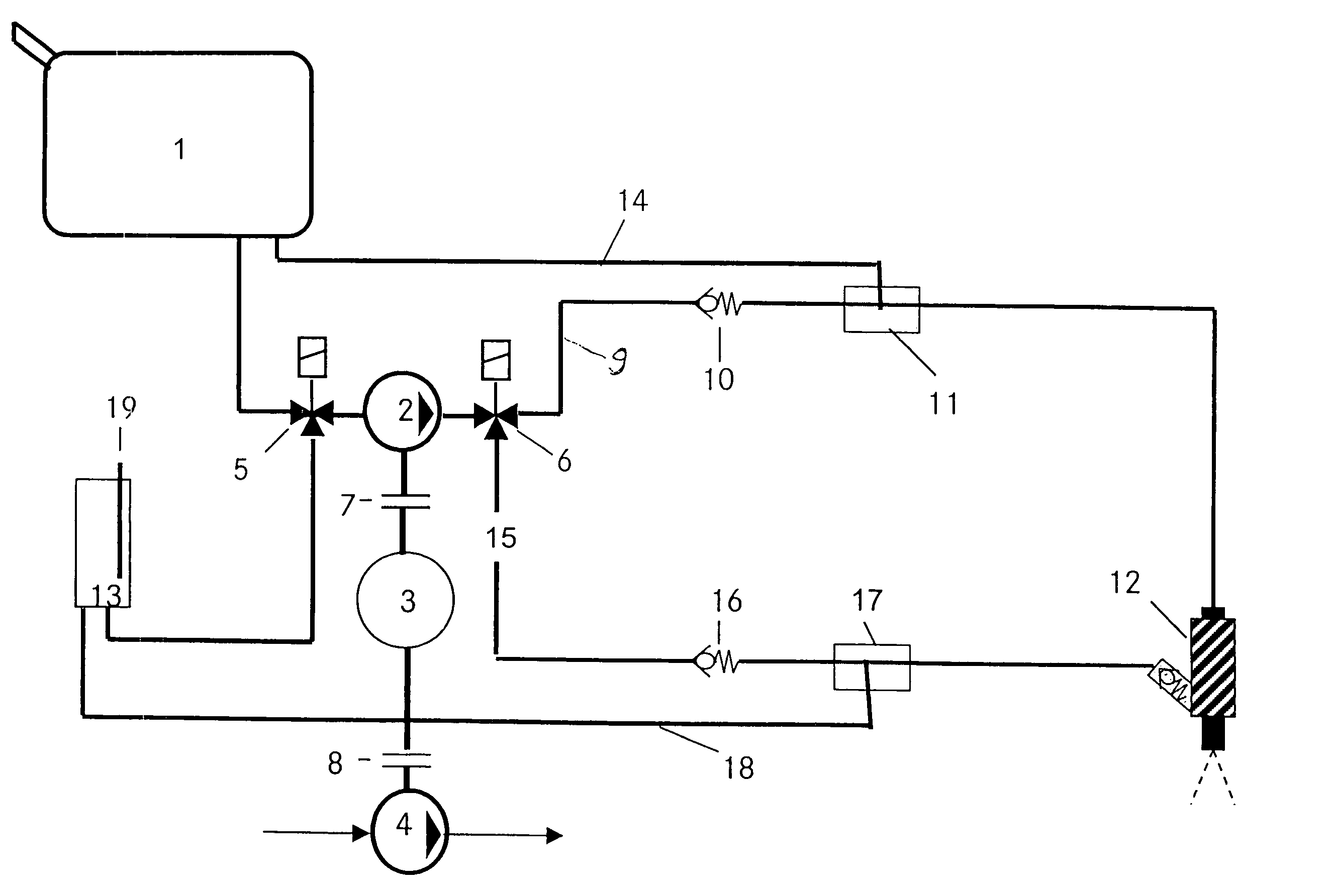
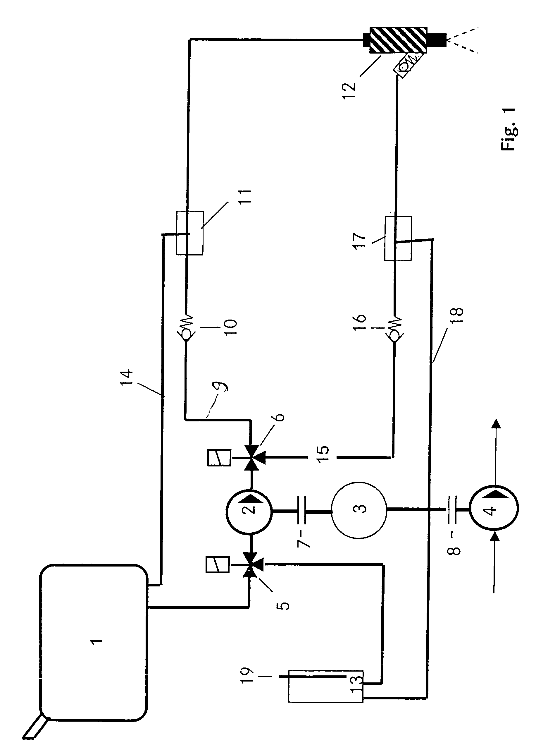
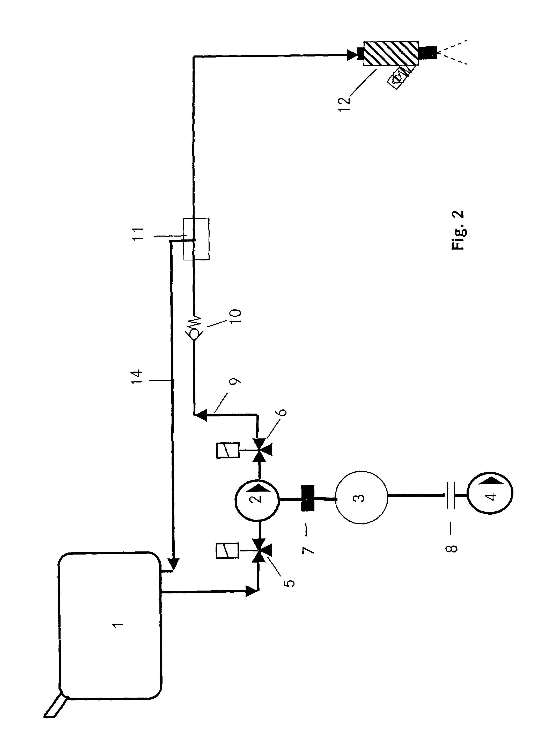
[0020]FIG. 1 shows the overall fuel supply system, the operating modes or functions of the installation being illustrated in FIGS. 2 to 6: Operation with main fuel, flushing with starting fuel, operation with starting fuel, first filling with starting fuel and the operation of the gas delivery pump, which will be explained below. The overall system advantageously permits, firstly, the production of starting fuel and, secondly, the simultaneous management of the delivery of main fuel and starting fuel.

[0021]FIG. 1 shows a pump unit comprising a fuel pump 2, an electric motor 3 and a gas delivery pump 4. A clutch 7 is provided between the fuel pump 2 and the electric motor 3, and a clutch 8 is provided between the electric motor 3 and gas delivery pump 4. The fuel pump 2, arranged between a valve 5 and 6, takes in the main fuel from the main fuel tank 1, given an appropriate position of the valve 5. Via a valve 6, the main fuel reaches the main fuel line 9 to the injection valve 12. B...


PUM


Abstract

In a fuel supply system for an internal combustion engine having two separate storage containers for liquid fuels, both connected to a first controllable valve which is connected, via a connecting line including a fuel pump to an inlet of a second controllable valve having two outlets in communication by separate fuel lines with a fuel injection nozzle of the internal combustion engine, each of the two separate fuel lines includes a fuel pressure regulator, one being in communication with one and the other with the other of the two separate fuel storage containers for returning exess fuel to the fuel storage container from which fuel is being supplied to the fuel injection nozzle.

Description

[0001]This is a Continuation-In-Part of International Application PCT / EP2003 / 011105 filed Oct. 8, 2003 and claiming the priority of German application 102 49 954.3 filed Oct. 26, 2002.BACKGROUND OF THE INVENTION[0002]The invention relates to a fuel supply system for an internal combustion engine having two separate fuel storage containers.[0003]A fuel supply system of this type is known from DE 197 34 493 C1. This fuel supply installation is provided with a fuel tank for liquid fuel, from which a fuel feed line leads to an injection apparatus, with an evaporation and condensing device for low boiling-point fuel fractions, which is connected to the fuel tank, with an intermediate tank for the condensate, connected after the evaporation and condensing device, from which a condensate line leads to a control valve controlling the supply to the injection device, and with a residual fuel return line discharging the higher boiling-point residual fuel fractions accumulating in the evaporati...

Claims


Application Information

Patent Timeline
Patent Type & Authority Patents(United States)
IPC IPC(8): F02M43/00F02D19/06F02D33/00F02M33/00F02M37/00F02M55/00F02M55/02
CPCF02D19/0605F02D33/003F02D33/006F02M33/00F02M37/0052F02M37/0064F02M37/0088F02M43/00F02D19/0621F02D19/0649F02D19/0684Y02T10/36F02M55/00F02M55/02F02D19/0628Y02T10/30
Inventor GLENZ, ANDREASHOENIG, GUENTERHOLDER, EBERHARDMATT, MARTINPOSSELT, ANDREAS
Owner DAIMLER AG
Why Eureka
Try Eureka