Reduced exhaust emissions gas turbine engine combustor

a technology of combustor and gas turbine engine, which is applied in the direction of hot gas positive displacement engine plants, combustion process, lighting and heating apparatus, etc., can solve the problems of increasing engine ownership and operational costs, and achieve the effect of reducing exhaust gas emissions during engine operation

Active Publication Date: 2009-03-24
HONEYWELL INT INC
View PDF35 Cites 16 Cited by
  • Summary
  • Abstract
  • Description
  • Claims
  • Application Information

AI Technical Summary

Benefits of technology

[0008]The present invention provides a gas turbine engine that includes a combustor that is configured to provide reduced exhaust gas emissions during engine operations.

Problems solved by technology

As a result, engine ownership and operational costs can increase.

Method used


Image

  • Reduced exhaust emissions gas turbine engine combustor
  • Reduced exhaust emissions gas turbine engine combustor
  • Reduced exhaust emissions gas turbine engine combustor

Examples


Embodiment Construction

[0016]Before proceeding with the detailed description, it is to be appreciated that the described embodiment is not limited to use in conjunction with a particular type of turbine engine. Thus, although the present embodiment is, for convenience of explanation, depicted and described as being implemented in a multi-spool turbofan gas turbine jet engine, it will be appreciated that it can be implemented in various other types of turbines, and in various other systems and environments.

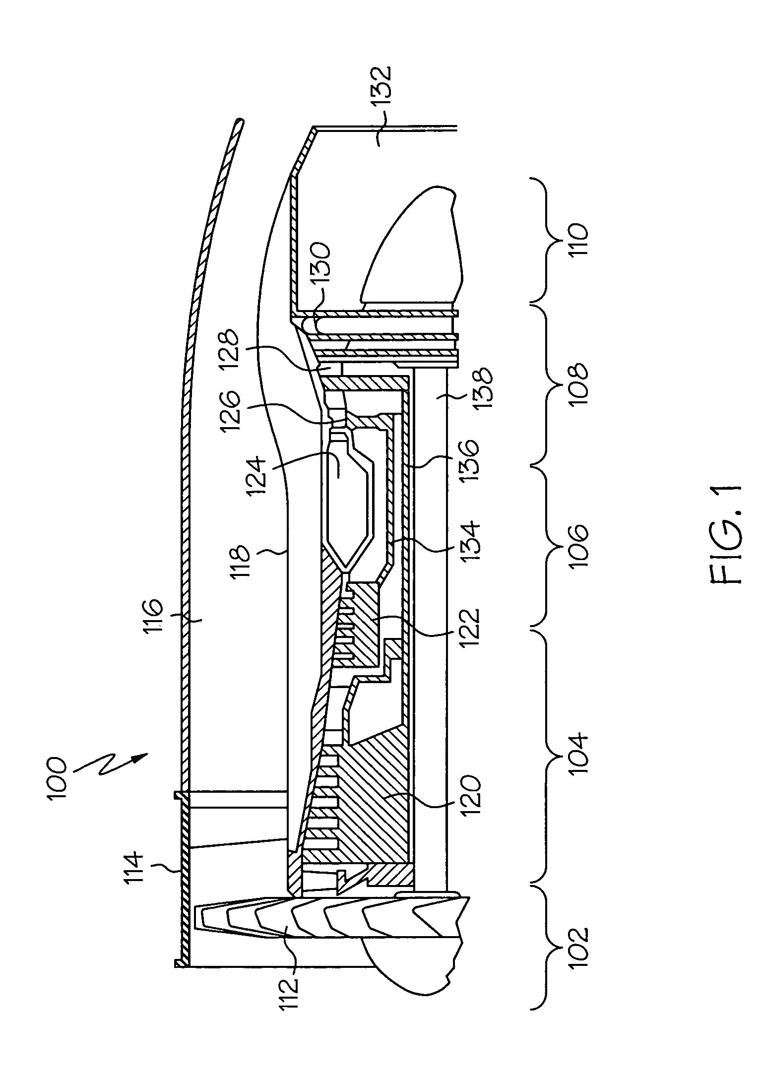
[0017]An exemplary embodiment of a multi-spool turbofan gas turbine jet engine 100 is depicted in FIG. 1, and includes an intake section 102, a compressor section 104, a combustion section 106, a turbine section 108, and an exhaust section 110. The intake section 102 includes a fan 112, which is mounted in a fan case 114. The fan 112 draws air into the intake section 102 and accelerates it. A fraction of the accelerated air exhausted from the fan 112 is directed through a bypass section 116 disposed betw...


PUM


Abstract

A gas turbine engine combustor includes a plurality of main fuel injector assemblies, and a plurality of pilot fuel injector assemblies, that are arranged and configured to reduce exhaust gas emissions during engine operation. The plurality of main fuel injector assemblies are arranged in a substantially circular pattern of a first radius, and each includes an outlet port having a first divergence angle. The plurality of pilot fuel injector assemblies are arranged in a substantially circular pattern of a second radius. Each pilot fuel injector assembly is disposed between at least two main fuel injector assemblies, and each includes an outlet port having a second divergence angle.

Description

STATEMENT REGARDING FEDERALLY SPONSORED RESEARCH OR DEVELOPMENT[0001]This invention was made with Government support under contract number NAS301136, awarded by the N.A.S.A. The Government has certain rights in this invention.FIELD OF THE INVENTION[0002]The present invention relates to gas turbine engines and, more particularly, to a gas turbine engine combustor that has reduced pollutant exhaust gas emissions.BACKGROUND OF THE INVENTION[0003]A gas turbine engine may be used to power various types of vehicles and systems. A particular type of gas turbine engine that may be used to power aircraft is a turbofan gas turbine engine. A turbofan gas turbine engine may include, for example, five major sections, a fan section, a compressor section, a combustor section, a turbine section, and an exhaust section. The fan section is positioned at the front, or “inlet” section of the engine, and includes a fan that induces air from the surrounding environment into the engine, and accelerates a ...

Claims


Application Information

Patent Timeline
Patent Type & Authority Patents(United States)
IPC IPC(8): F02C1/00F02G3/00F23R3/28F23R3/34
CPCF23R3/286F23R3/343
Inventor ZUPANC, FRANK J.YANKOWICH, PAUL R.BARTON, MICHAEL T.
Owner HONEYWELL INT INC
Why Eureka
Try Eureka