Fuel cell system and method with increased efficiency and reduced exhaust emissions

a fuel cell and efficiency technology, applied in the direction of electrochemical generators, separation processes, transportation and packaging, etc., can solve the problems of undesired thermochemical reactions, inefficiencies and undesired side effects in the process, and 18% of the total input gas is actually available, so as to improve the efficiency of fuel cell operation, reduce undesired exhaust gas emissions, and improve the arrangement and operation method of the fuel cell

Inactive Publication Date: 2007-04-24
AIRBUS OPERATIONS GMBH
View PDF10 Cites 18 Cited by
  • Summary
  • Abstract
  • Description
  • Claims
  • Application Information

AI Technical Summary

Benefits of technology

[0010]In view of the above, it is an object of the invention to provide a fuel cell arrangement and a method for increasing the efficiency of fuel cells operated with input air and hydrogen or hydrocarbon fuel, and to simultaneously reduce undesired exhaust gas emissions from the operation of the fuel cells. It is a further object of the invention to provide an improved fuel cell arrangement and operating method, which can very effectively and efficiently be used for generating electrical power as well as useable water onboard an aircraft. The invention further aims to avoid or overcome the disadvantages of the prior art, and to achieve additional advantages, as apparent from the present specification.
[0013]The arrangement may further comprise a molecular sieve that receives the exhaust or output gases of the high temperature fuel cell or the reformer, and selectively separates hydrogen therefrom. This hydrogen or hydrogen enriched gas is then provided back to the fuel cell system, particularly to the low temperature fuel cell as the fuel for operating the low temperature fuel cell. Thus, the fully developed arrangement according to the invention includes oxygen enrichment for the oxidizer gas input of the fuel cell system, particularly the low temperature fuel cell and the high temperature fuel cell, by using the oxygen generator, as well as hydrogen enrichment of the fuel gas for the low temperature fuel cell by reprocessing the exhaust gases of the high temperature fuel cell through a molecular sieve to provide hydrogen or hydrogen enriched gas as a fuel to the low temperature fuel cell as well as useable water as a byproduct. Thereby, the efficiency of the system is increased, and the exhaust gas emissions are reduced.

Problems solved by technology

This means that only 18% of the total input gas is actually available for use in the fuel cell, while approximately 82% of the input gas supplied to the oxygen side of the fuel cell is not useable in the fuel cell reaction process.
That necessarily leads to inefficiencies and undesired side effects in the process.
In the case of high temperature fuel cells, which operate at temperatures in the range of about 600 to 1000° C., this further leads to undesired thermochemical reactions, such as the formation of nitrogen oxides (NOX).
These undesired byproduct gases become pollutant components of the output exhaust gas.

Method used


Image

  • Fuel cell system and method with increased efficiency and reduced exhaust emissions
  • Fuel cell system and method with increased efficiency and reduced exhaust emissions
  • Fuel cell system and method with increased efficiency and reduced exhaust emissions

Examples


Embodiment Construction

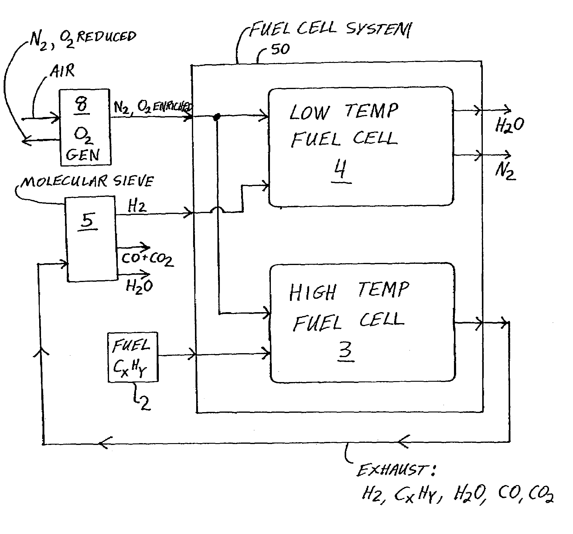
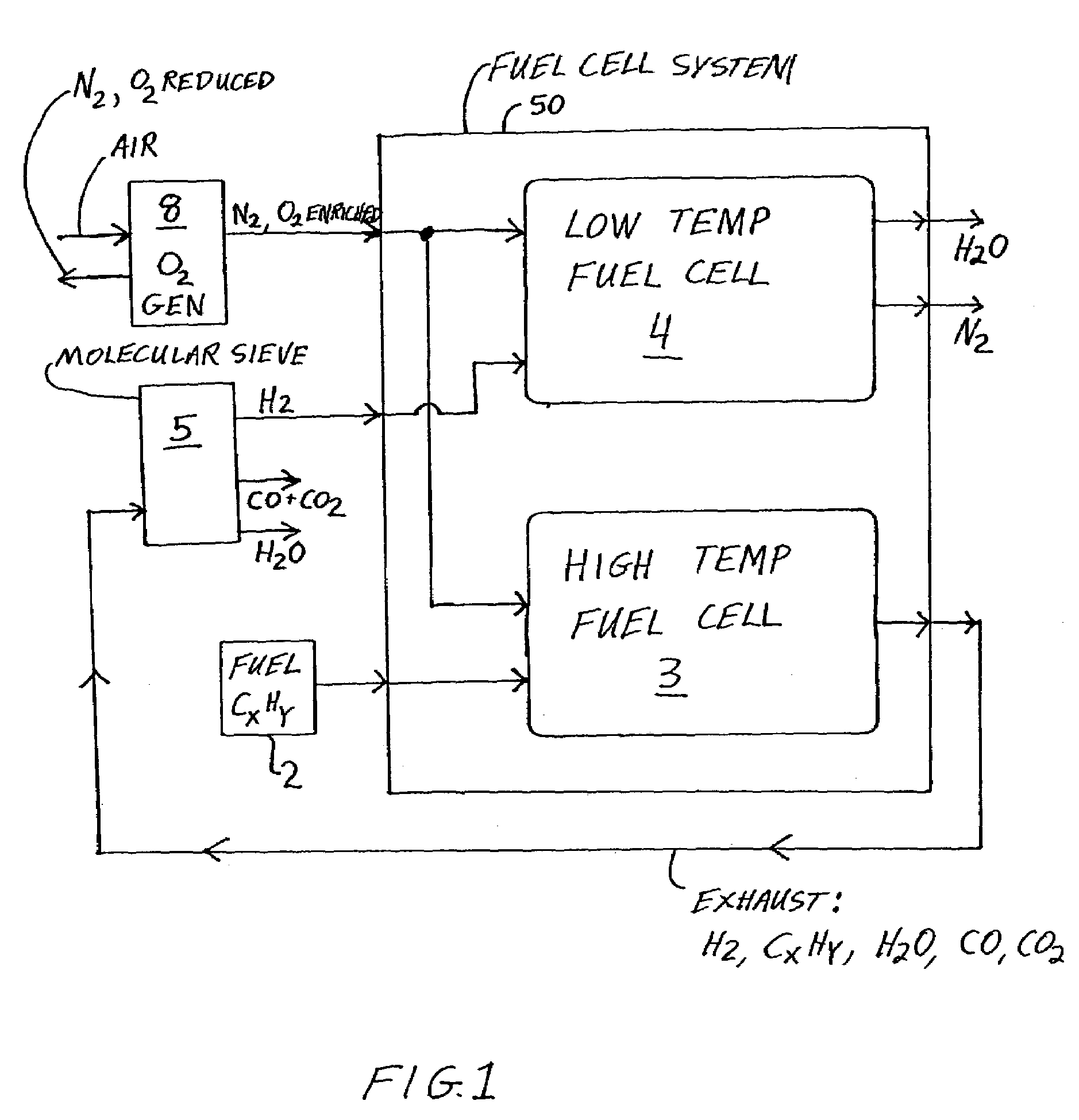
[0020]FIG. 1 is a greatly simplified schematic block diagram showing the major components and connections of a fuel cell arrangement according to a first embodiment of the invention. Only the principle inputs and outputs of each block are shown, while many inputs and outputs have been omitted for simplicity in explaining the principle features, functions and operation of the arrangement.

[0021]This embodiment of the fuel cell arrangement shown in FIG. 1 includes a fuel cell system 50, an oxygen enrichment device or oxygen generator 8, a molecular sieve 5, and a hydrocarbon fuel supply 2, for example supplying kerosene or jet fuel. The fuel cell system 50 includes a low temperature fuel cell 4 (e.g. PEMFC), as well as a high temperature fuel cell 3 (e.g. SOFC). The oxygen generator 8 receives an input of environmental air, and provides an output of oxygen enriched air or gas, predominantly comprising nitrogen (N2) and an enriched proportion of oxygen (O2) in comparison to the input ai...


PUM

PropertyMeasurementUnit
temperatureaaaaaaaaaa
temperaturesaaaaaaaaaa
temperatureaaaaaaaaaa

Abstract

An apparatus includes a low temperature fuel cell, a high temperature fuel cell or a hydrocarbon reformer, a hydrocarbon fuel supply, an oxygen generator, and a molecular sieve. The oxygen generator separates air to provide oxygen enriched air to the fuel cells and the reformer. Hydrocarbon fuel is provided to the high temperature fuel cell or the reformer, and the exhaust gas thereof may be separated through the molecular sieve, to provide hydrogen enriched gas to the low temperature fuel cell, water, carbon monoxide, and carbon dioxide. The low temperature fuel cell outputs nitrogen gas and high purity water. The emitted carbon oxides and nitrogen oxides are catalytically converted to nitrogen and carbon dioxide being returned to the atmosphere. The process and apparatus are very efficient, produce high purity water and electrical energy, and are environmentally friendly.

Description

PRIORITY CLAIM[0001]This application is based on and claims the priority under 35 U.S.C. §119 of German Patent Application 102 16 361.8, filed on Apr. 13, 2002, the entire disclosure of which is incorporated herein by reference.FIELD OF THE INVENTION[0002]The invention relates to a method for increasing the efficiency and reducing the exhaust emissions of a fuel cell system, especially a system for generating energy and water from one or more fuel cells. The invention further relates to a fuel cell arrangement for carrying out such a method.BACKGROUND INFORMATION[0003]A fuel cell is an electrochemical cell that converts chemical energy directly into electrical energy through a chemical reaction between an electrolyte, a fuel, and an oxidizer. The use of fuel cells is becoming of ever-greater interest as a potentially cleaner and more efficient manner of producing electrical energy, in comparison to combustion-based power generation processes and systems. For operating a fuel cell, g...

Claims


Application Information

Patent Timeline
Patent Type & Authority Patents(United States)
IPC IPC(8): H01M8/06H01M8/04B01D53/02B64D11/02B64D41/00H01M8/24
CPCB01D53/02B64D11/02B64D41/00H01M8/0612H01M8/2495H01M8/04089B64D2041/005Y02T90/36Y02E60/50Y02T90/40
Inventor HOFFJANN, CLAUSHEINRICH, HANS-JUERGEN
Owner AIRBUS OPERATIONS GMBH
Why Eureka
Try Eureka