Motor-driven hand-held tool with functional step display

a technology of functional step and hand-held tools, which is applied in the direction of portable power-driven tools, drilling machines, contacts, etc., can solve the problems of high manufacturing cost of hand-held tools associated with the use damage or disruption of operation of such display means, and the actual functional step is reliable and the functional display means is cost-effective. , the effect of reliable display

Active Publication Date: 2006-04-18
HILTI AG
View PDF13 Cites 16 Cited by
  • Summary
  • Abstract
  • Description
  • Claims
  • Application Information

AI Technical Summary

Benefits of technology

[0011]The advantage of spacing of the functional step display means from the switching recess consists in that it can be made, on one hand, very robust from the mechanical point of view and, on the other hand, the display means provides for a good serviceability of the actuation member and for an optimal visibility of the identification marks. In addition, the provision of a read-out device, which forms part of display means and is, thus separated form the actuation member, provides additional possibility of displaying of more than two functional steps.
[0012]Advantageously, the display means is formed by a recess provided in the housing, with both the switching recess and the display means recess being formed in an upper, with respect to the handle, surface or side of the housing. Thereby, on one hand, during an operation, a good visibility of marks is insured. On the other hand, because of the provision of both recesses on the upper side of the housing, the housing can be cost-effectively produced by casting.
[0015]Advantageously, the slide member is provided with at least one locking member adapted to engage in a respective matching locking element provided on the housing at least in two positions of the slide member relative to the housing. In this way, predetermined positions for the slide member and the actuation member relative to the housing can be established in which the functional steps are precisely set and with which, a disturbance-free shifting of the functional unit is insured. A further advantage of the locking means according to the present invention consists in that the locking positions can be so selected that the mark, which corresponds to a respective functional step, is completely visible in the display means, with other marks being completely covered by the housing.
[0016]Advantageously, the actuation member is formed on the slide member in order to achieve as direct as possible actuation of the slide member during the shifting process, which insures a reliable display of the actual functional step. Further, forming the actuation member, the slide member, and the read-out element as a one-piece part provides for a very cost-effective manufacturing of the functional display means.

Problems solved by technology

The drawback of both solutions, those of U.S. Pat. No. 6,364,580 and German Publication DE-2933355, consists in that, on one hand, with mechanically operated functional step display means, only two functional steps can be displayed, and the display is effected by the actuation member.
Therefore, the known functional step displays are not suitable for functional units having more than two functional steps, such as, e.g., a three-speed gearset.
On the other hand, with many hand-held power tools, it is either very difficult to use the actuation member in such a way that a good visibility of the functional step display is insured or, vise versa, the functional step display, in particular during operation, is hardly visible in order to provide for good access to the actuation member.
The drawback of electronically operated display means consists in high manufacturing costs of hand-held tool associated with the use of such display means.
Moreover, vibrations and impacts that act on hand-held tool during operation, lead often to damage or disruption of operation of such display means.

Method used


Image

  • Motor-driven hand-held tool with functional step display
  • Motor-driven hand-held tool with functional step display
  • Motor-driven hand-held tool with functional step display

Examples


Embodiment Construction

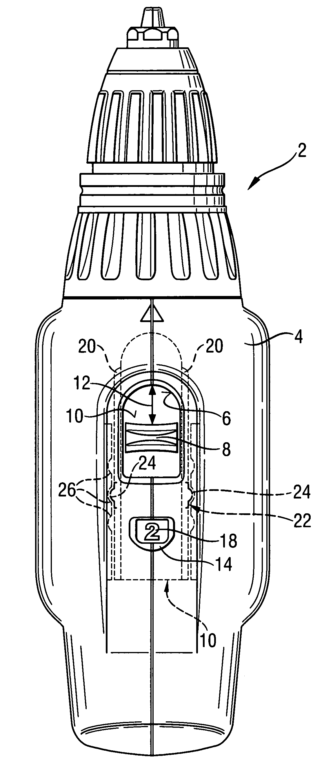
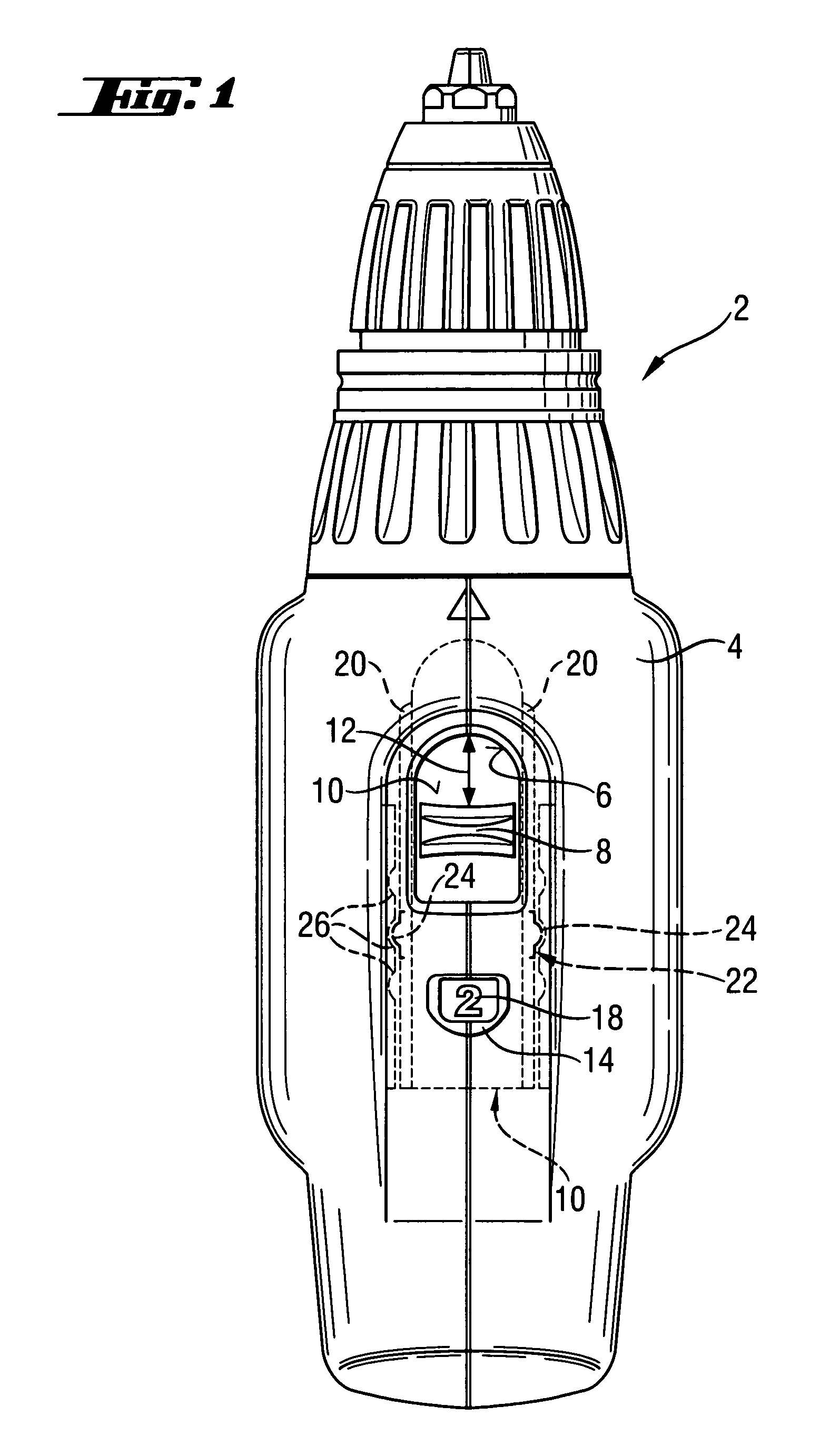
[0022]FIG. 2 shows an upper, remote from a handle (not shown), side of a hand-held power tool 2 which is formed as a drilling and screw-driving tool. The hand-held power tool has a housing 4 in which a switching recess 6 is formed. Through the switching recess 6, an actuation member 8 in form of a slide switch projects. The slide switch is provided on an upper side of a slide member 10. The actuation member 8 is used, together with the slide member 10 for switching between three-speeds of a gearset (not shown). To this end, the slide member 10 is supported on the inner side of the housing 4 for reciprocating movement in an actuation direction 12, shown with a double arrow.

[0023]As shown with dash lines, in an invisible region of the housing 4, the slide member 10 projects above display means 14 formed as a recess in the housing 4, with the display means 14 being spaced from the switching recess 6 in the actuation direction 12.

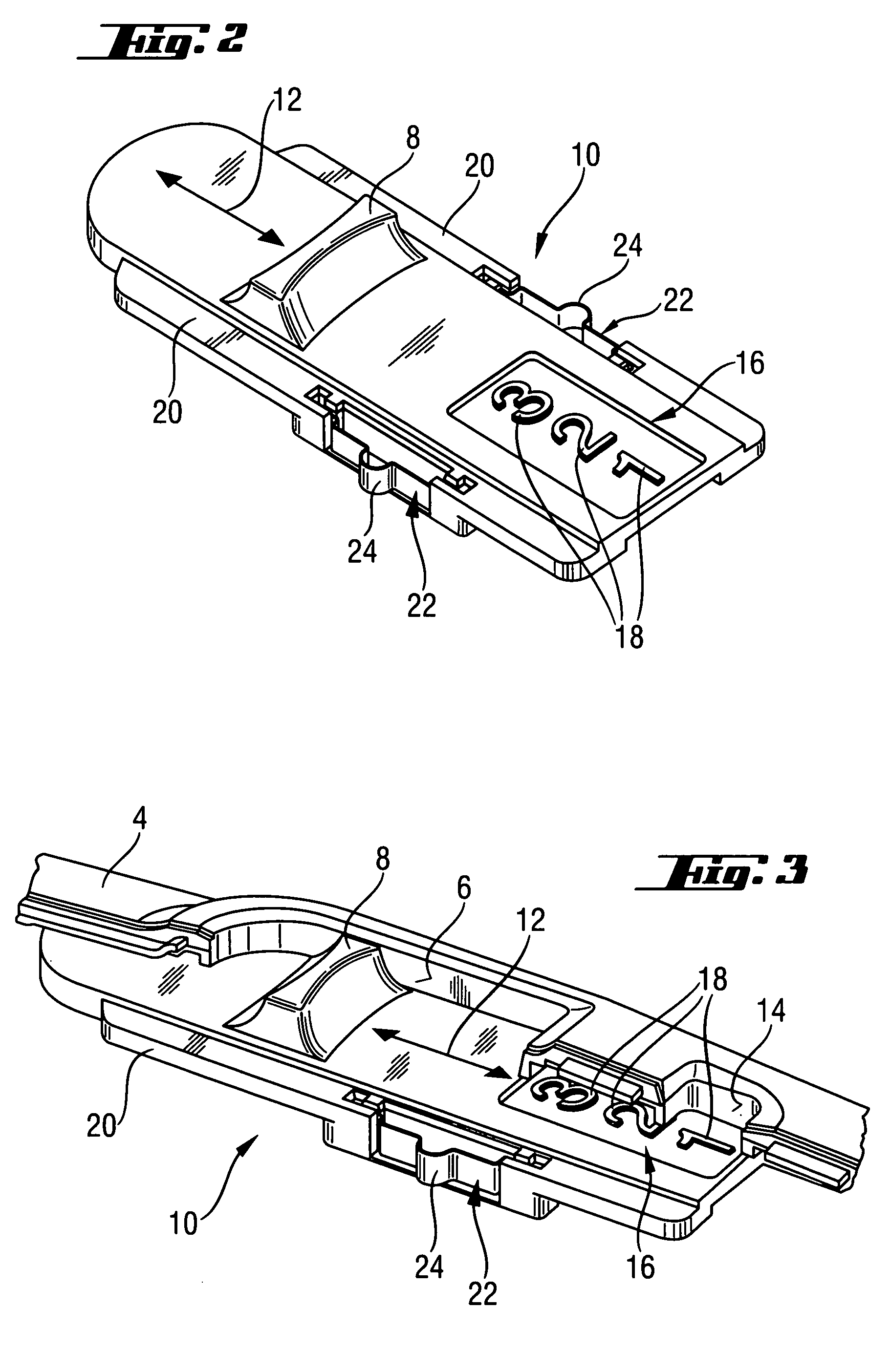
[0024]FIGS. 2 and 3 show a detailed view of the slide mem...


PUM

PropertyMeasurementUnit
speedsaaaaaaaaaa
speedaaaaaaaaaa
rotational speedaaaaaaaaaa

Abstract

A motor-driven hand-held tool includes a housing (4) having a switching recess (6) formed therein, an actuation member (8) displaceably arranged in the switching recess for shifting a functional unit between different functional steps, and and a functional step display arrangement having a read-out device (16) mechanically connected with the actuation member (8) and a display element (14) provided in the housing (4) for displaying an actual functional step and spaced from the switching recess (6).

Description

BACKGROUND OF THE INVENTION[0001]1. Field of the Invention[0002]The present invention relates to a motor-driven hand-held tool, including a housing having a switching recess formed therein, an actuation member displaceably arranged in the switching recess for shifting a functional unit between different functional steps, and a functional step display arrangement having a read-out device mechanically connected with the actuation member and a display element provided in the housing for displaying an actual functional step.[0003]2. Description of the Prior Art[0004]Motor-driven hand-held tools have usually several functional units which, as required, are shifted between different functional steps such as, e.g. speeds or rotational directions. In order for a hand-held tool user to know, during an operation, at each moment, which functional step is set, many conventional hand-held tools are provided, mostly on the housing, with functional step display means that display an actual functio...

Claims


Application Information

Patent Timeline
Patent Type & Authority Patents(United States)
IPC IPC(8): B25B23/145B25F5/00
CPCB25F5/001
Inventor BREITENMOSER, ARMIN
Owner HILTI AG
Why Eureka
Try Eureka