Systems and methods for controllably refilling a fluid quantity sensing fluid ejection head

a technology of fluid ejection head and fluid quantity, which is applied in the direction of printing, etc., can solve the problems of frequent fluid metering, high cost of umbilical system, and low efficiency of periodic ejection system, so as to reduce the productivity of fluid ejection device, increase the frequency of refill operations, and save space

Inactive Publication Date: 2006-04-18
FUJIFILM BUSINESS INNOVATION CORP
View PDF9 Cites 8 Cited by
  • Summary
  • Abstract
  • Description
  • Claims
  • Application Information

AI Technical Summary

Benefits of technology

[0007]Periodic refill systems commonly do not accurately meter the fluid that is deposited into the fluid ejector. Consequently, the fluid reservoir in a fluid ejector must be significantly underfilled in order to avoid excess fluid spilling out of the refilled fluid reservoir. Consequently, this under-filling wastes space and reduces the productivity of the fluid ejection device due to the greater frequency of refill operations.

Problems solved by technology

Replacing cartridges requires frequent interaction by the user, and is considered disadvantageous for fluid ejectors used in volume production or connected by a network to the ejection data source.
Umbilical systems can be expensive, requiring pressurization, tubing, tube harness dressing, and can suffer performance degradation from moisture loss, pressure fluctuations due to acceleration or temperature variation, and motion hysterisis from tubing harness drag.
Periodic refill systems commonly do not accurately meter the fluid that is deposited into the fluid ejector.
Consequently, this under-filling wastes space and reduces the productivity of the fluid ejection device due to the greater frequency of refill operations.

Method used


Image

  • Systems and methods for controllably refilling a fluid quantity sensing fluid ejection head
  • Systems and methods for controllably refilling a fluid quantity sensing fluid ejection head
  • Systems and methods for controllably refilling a fluid quantity sensing fluid ejection head

Examples


Embodiment Construction

[0033]The following detailed description of various exemplary embodiments of the fluid ejection systems according to this invention may refer to one specific type of fluid ejection system, e.g., an inkjet printer, for sake of clarity and familiarity. However, it should be appreciated that the principles of this invention, as outlined and / or discussed below, can be equally applied to any known or later-developed fluid ejection systems, beyond the fluid jet printer specifically discussed herein.

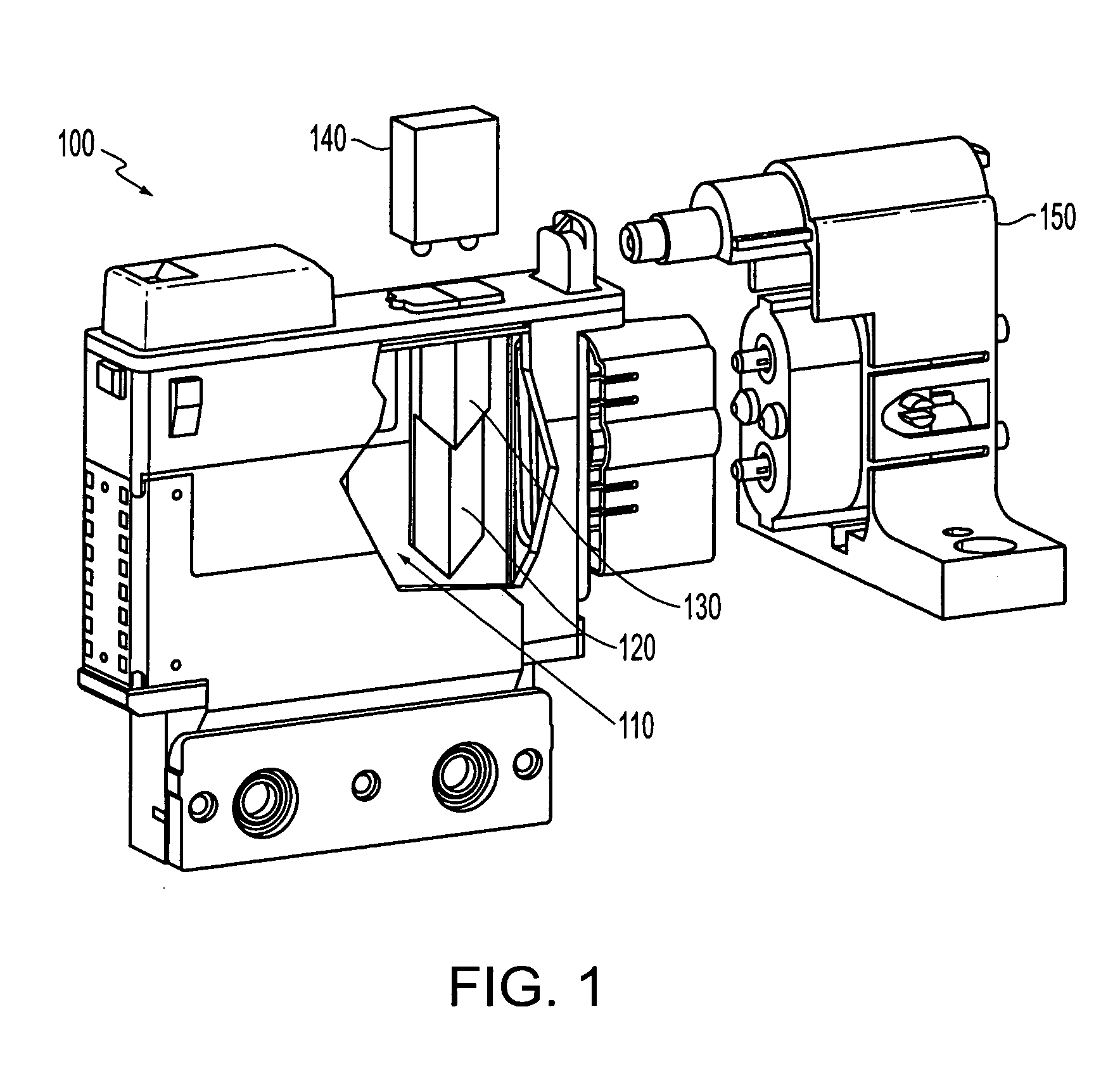
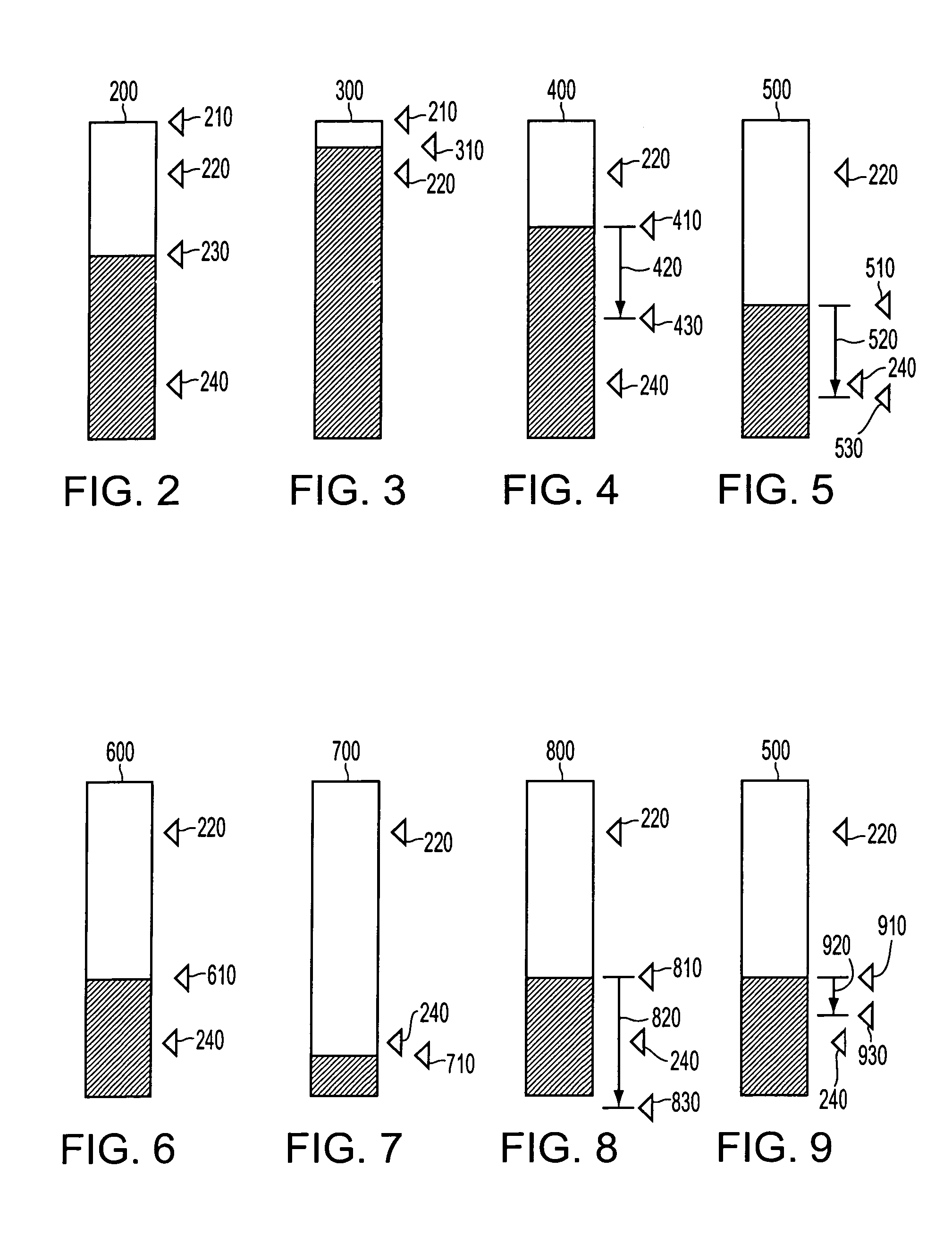
[0034]A fluid ejector, such as, for example, an inkjet printhead, is produced, distributed and / or installed with a fluid reservoir, such as, for example, an ink reservoir, typically filled with a fluid, such as, for example, ink. The fluid ejector, includes, in accordance with this invention, instrumentation to measure fluid level of the fluid that the fluid reservoir holds. One exemplary device usable to indicate the fluid level is a prism into which light is projected. The injected light is e...


PUM


Abstract

A controller for a fluid ejecting system having a refillable container includes an ejection count initializing circuit, routine or application, a count incrementing circuit, routine or application, at least one fluid level indicator, and a fluid quantity circuit, routine or application for determining an expended quantity of fluid, a fluid reserve capacity circuit, routine or application for determining a fluid reserve capacity in the container, an ejection job determining circuit, routine or application for determining a fluid job requirement, a reserve comparing circuit, routine or application to compare the fluid reserve capacity and the fluid job requirement, and a refill condition determining circuit, routine or application to determine that the container is to be refilled. Counts for a ejection amount and a reserve capacity are incremented in response to a specific amount of fluid being ejected from the container. The expended quantity of fluid is based on the ejection amount count subsequent to the fluid level being indicated. The fluid reserve capacity is based on the reserve capacity count and the expended quantity of fluid. The fluid job requirement is based on the expended quantity of fluid and a job number of ejected amounts of fluid. The container is determined to be refilled upon at least a condition wherein the fluid job requirement exceeds the fluid reserve capacity, and a condition wherein the fluid level is below a refill threshold.

Description

BACKGROUND OF THE INVENTION[0001]1. Field of Invention[0002]This invention relates to controlling fluid quantity in a fluid ejection head.[0003]2. Description of Related Art[0004]Fluid ejector systems, such as drop-on-demand liquid ink printers, have at least one fluid ejector from which droplets of fluid are ejected towards a receiving sheet. For example, scanning inkjet printers are equipped with printheads containing fluid ink. The fluid is applied to a sheet in an arrangement based on print data received from a computer, a scanner or similar device. To control the delivery of the fluid to the sheet, fluid ejection heads are moved across the sheet to provide the fluid to the sheet, which is ejected as drops. Each drop corresponds to a liquid volume designated as a pixel. Each pixel is related to a quantity needed to darken or cover a particular unit area.[0005]In order to lower cost and improve performance by limiting inertia, moving-head fluid ejection systems are designed with ...

Claims


Application Information

Patent Timeline
Patent Type & Authority Patents(United States)
IPC IPC(8): B41J2/195B41J2/175
CPCB41J2/17566B41J2/17509
Inventor MERZ, ERIC A.HILTON, BRIAN S.
Owner FUJIFILM BUSINESS INNOVATION CORP
Why Eureka
Try Eureka