Ink-jet recording device and control method thereof

a recording device and inkjet technology, applied in the direction of printing, other printing devices, etc., can solve the problems of ink cartridge erroneously being removed, ink ejection malfunctions occurring at the recording head, and the size of the waste ink reservoir is reduced, and prevent the leakage of ink

Inactive Publication Date: 2006-04-18
PANASONIC CORP
View PDF11 Cites 13 Cited by
  • Summary
  • Abstract
  • Description
  • Claims
  • Application Information

AI Technical Summary

Benefits of technology

[0023]It is, therefore, one objective of the present invention to provide an ink-jet recording device and a control method thereof that can prevent the entry into an ink flow path of air bubbles when a detachable ink supply member is externally removed.
[0024]Further, one objective of the present invention to provide an ink-jet recording apparatus for which the size of a waste ink reservoir is reduced.
[0025]Still further, one objective of the present invention to provide an ink-jet recording device that can prevent the leakage of ink inside the device when a detachable waste ink reservoir is externally removed.
[0026]According to a first aspect of the present invention, an ink-jet recording device includes: a medium feeding unit, arranged inward of a predetermined face of a main body, for feeding a recording medium; a medium ejection unit, arranged inward of the same face as the medium loading unit, for ejecting the recording medium after recording; an ink supply member loading unit, arranged inward of the same face as the medium loading unit, for detachably loading an ink supply member wherein ink used for recording is retained; and a removal inhibition unit for disabling removal of the ink supply member during a removal inhibited period for the ink supply member, thereby being able to prevent the entry into an ink flow path of air bubbles when a detachable ink supply member is externally removed.
[0027]According to a second aspect of the present invention, an ink-jet recording device includes: a medium feeding unit, arranged inward of a predetermined face of a main body, for feeding a recording medium; a medium ejection unit, arranged inward of the same face as the medium loading unit, for ejecting the recording medium after recording; an ink supply member loading unit, arranged inward of the same face as the medium loading unit, for detachably loading an ink supply member wherein ink used for recording is retained; an operation detector for detecting the start of an ink supply member removal operation; and a removal controller for, when during the removal inhibited period the operation detector has detected the start of the ink supply member removal operation, shifting the ink-jet recording device to the recording standby state to enable the removal of the ink supply member, thereby being able to prevent the entry into an ink flow path of air bubbles when a detachable ink supply member is externally removed.
[0028]According to a sixth aspect of the present invention, an ink-jet recording device includes: a medium feeding unit, arranged inward of a predetermined face of a main body, for feeding a recording medium; a medium ejection unit, arranged inward of the same face as the medium loading unit, for ejecting the recording medium after recording; an ink supply member loading unit, arranged inward of the same face as the medium loading unit, for detachably loading an ink supply member wherein ink used for recording is retained; a removal detector for detecting removal of the ink supply member; and a removal controller for, when during the removal inhibited period the removal detector detects that the ink supply member has been removed, shifting the ink-jet recording device to the recording standby state, thereby being able to prevent the entry into an ink flow path of air bubbles when a detachable ink supply member is externally removed.

Problems solved by technology

However, the ink-jet recording device has the following problems.
However, the thus arranged ink-jet recording device has the following problems.
While an ink cartridge can be easily attached / detached to / from the front face of the device, the ink cartridge may erroneously be removed, which in this case may produce the following defective results.
First, when an ink cartridge is removed during a period such as a recording period, while ink is flowing from the ink cartridge to the recording head, air bubbles will enter the ink flow path at the location whereat the ink cartridge and the main body of the device are connected, and an ink ejection malfunction may thereafter occur at the recording head.
Further, additional time is also required for this discharging operation.

Method used


Image

  • Ink-jet recording device and control method thereof
  • Ink-jet recording device and control method thereof
  • Ink-jet recording device and control method thereof

Examples


embodiment 1

[0074](Embodiment 1)

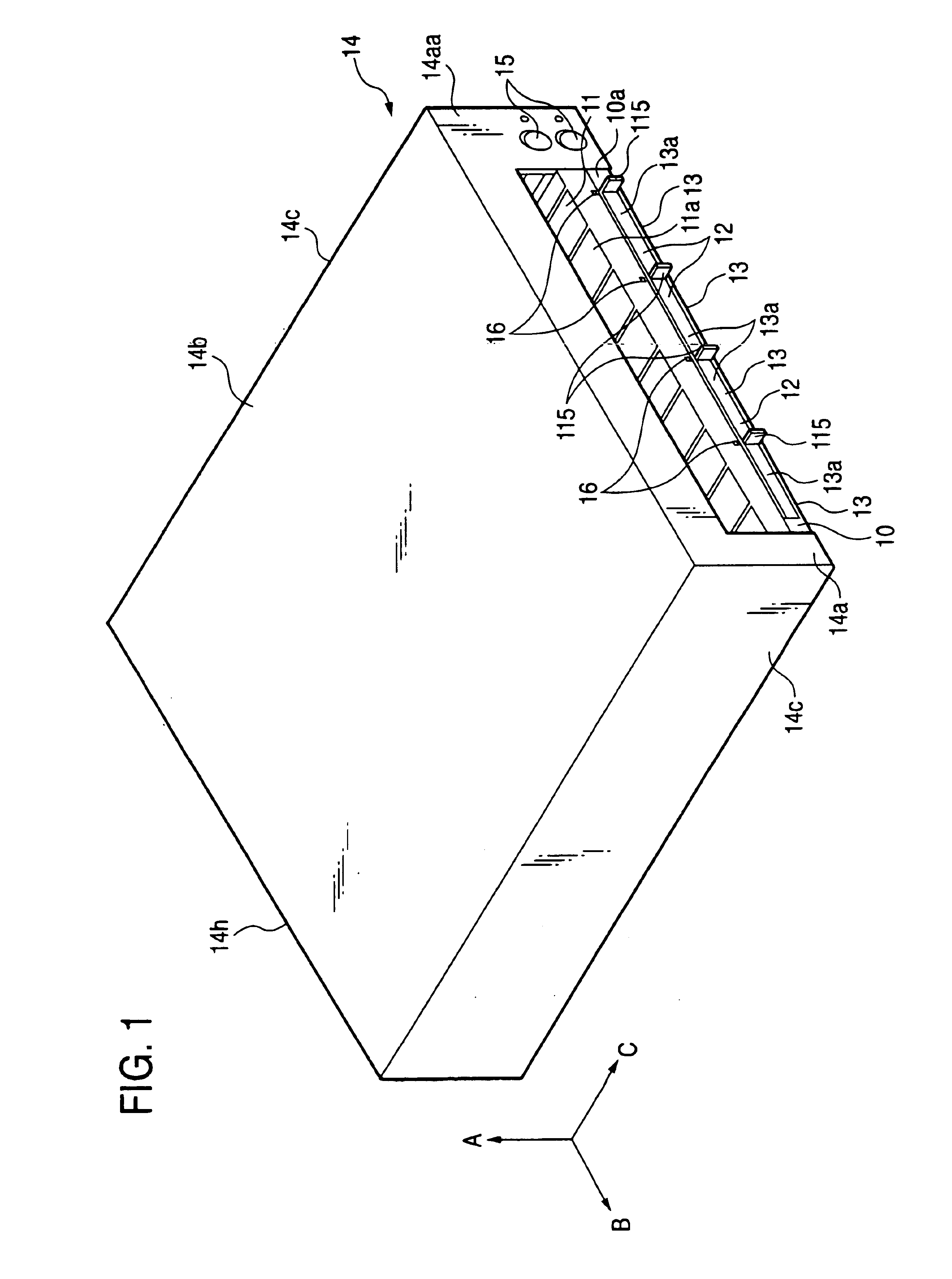
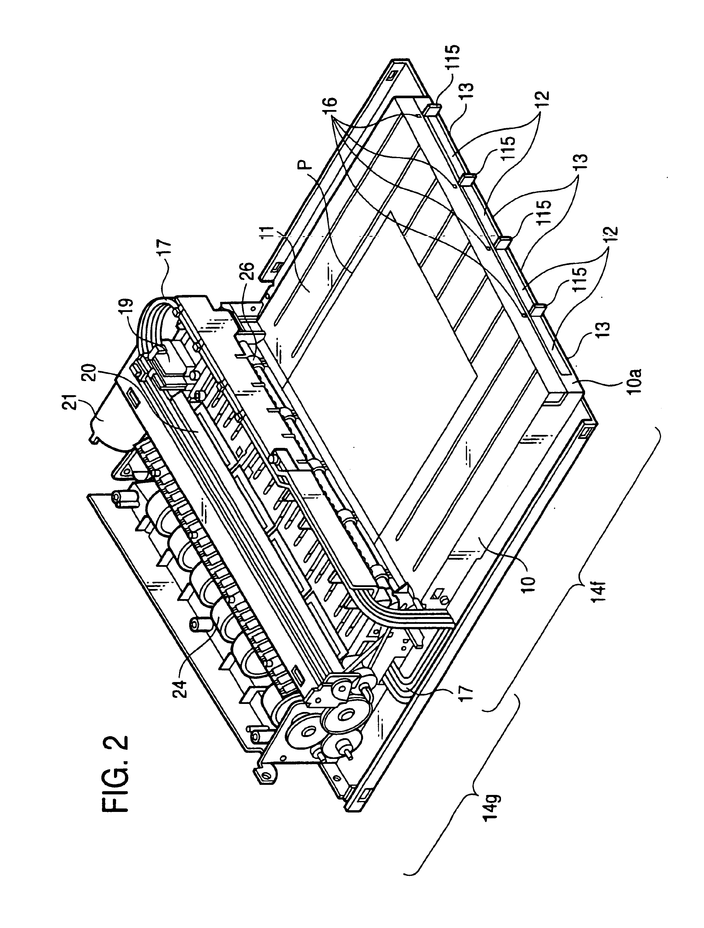
[0075]FIG. 1 is a perspective view of the exterior of an ink-jet recording device according to a first embodiment of the invention. FIG. 2 is a perspective view of the internal structure of the ink-jet recording device in FIG. 1. FIG. 3 is a side view of the internal structure of the ink-jet recording device in FIG. 1. FIG. 4 is an explanatory diagram, showing a control mechanism provide for the ink-jet recording device in FIG. 1, wherein an ink cartridge has been removed. FIG. 5 is an explanatory diagram, showing the control mechanism of the ink-jet recording device in FIG. 1, wherein the loading of the ink cartridge is being performed. FIG. 6 is an explanatory diagram, showing the control mechanism of the ink-jet recording device in FIG. 1, wherein the ink cartridge has been loaded. FIG. 7 is an explanatory diagram, showing the control mechanism of the ink-jet recording device in FIG. 1, wherein removal of the ink cartridge has been disabled. FIG. 8 is an expla...

embodiment 2

[0114](Embodiment 2)

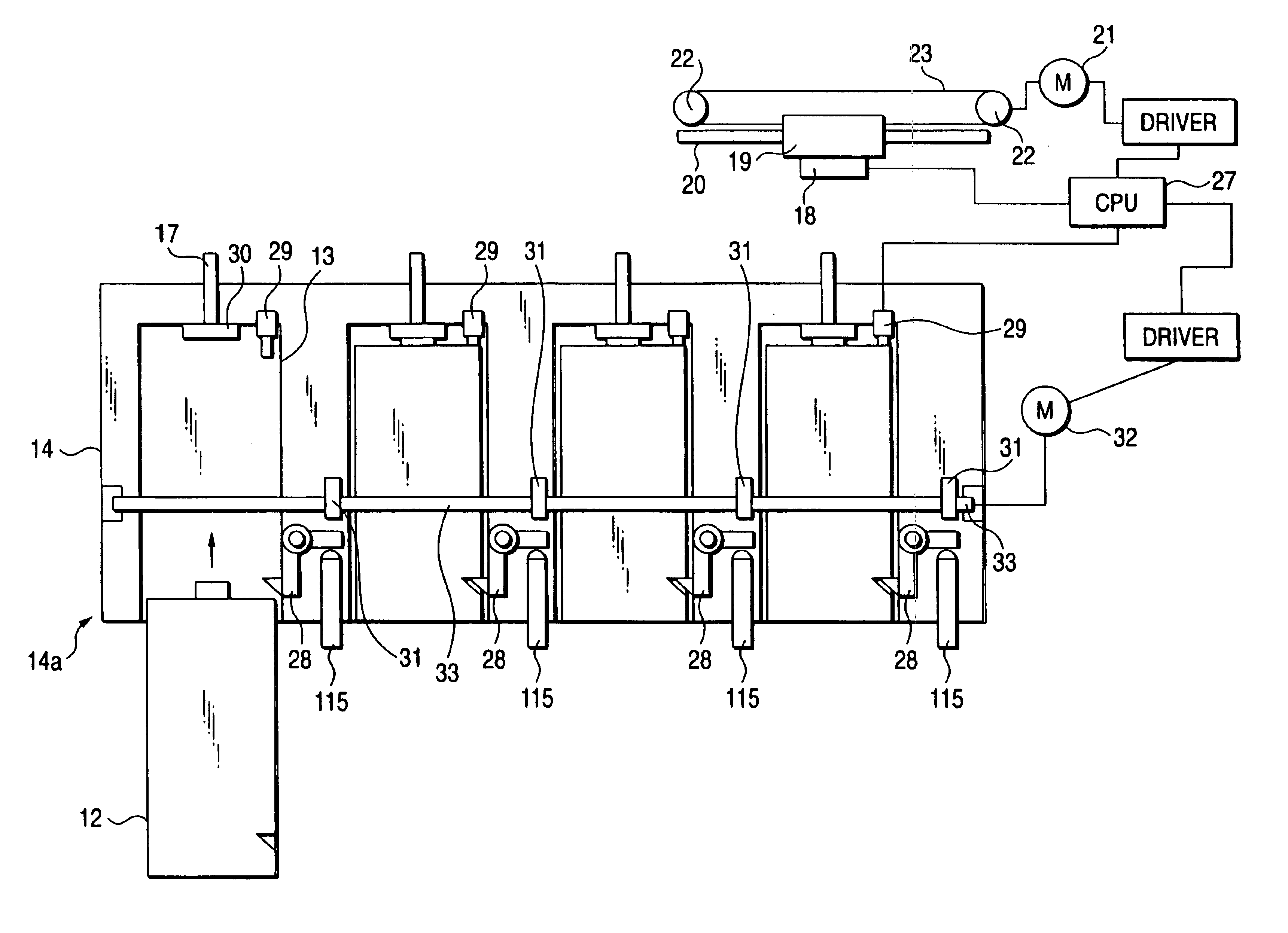
[0115]FIG. 9 is an explanatory diagram, showing an ink-jet recording device according to a second embodiment of the invention, wherein a control mechanism disables removal of an ink cartridge. FIG. 10 is an explanatory diagram, showing the ink-jet recording device according to the second embodiment of the invention, wherein the control mechanism allows the removal of the ink cartridge.

[0116]It should be noted that for the second to fourth embodiments, the exterior and the internal configuration of the ink-jet recording device are substantially the same as those shown in FIGS. 1 to 3 for the first embodiment.

[0117]In this embodiment, a controller 27 is provided that disables removal of ink cartridges 12 during a removal inhibited period, and prevents air bubbles from entering ink flow paths due to the removal of the ink cartridges 12, which can be directly detachable, externally.

[0118]As shown in FIGS. 9 and 10, the ink-jet recording device includes: actuators (ho...

embodiment 3

[0124](Embodiment 3)

[0125]FIGS. 11A and 11B are explanatory diagrams, showing an ink-jet recording device according to a third embodiment of the present invention, wherein a control mechanism detects the start of an ink cartridge removal operation. FIG. 11A shows the state wherein the ink cartridge removal operation has not yet started. FIG. 11B shows the state wherein the ink cartridge removal operation has started. To simplify the illustration, a control system is shown only in FIG. 11B.

[0126]As shown in FIGS. 11A and 11B, a door 35, provided for the front face of an ink cartridge loading unit 13, can be opened or closed when an ink cartridge 12 has been inserted into the ink cartridge loading unit 13.

[0127]An operation detector 36 is also provided that detects the opening or closing of the door 35, and determines whether the removal of the ink cartridge 12 should be started when the door 35 is opened.

[0128]Further, a controller (removal controller) 37 is also provided. Thus, duri...


PUM


Abstract

An ink-jet recording device according to the present invention includes: a paper supply tray arranged inward of a predetermined face of a main body to supply recording sheets; a paper display tray arranged inward of the same face as the paper supply tray to receive recording sheets discharged after recording; an ink cartridge loading unit, which is arranged inward of the same face as the paper supply tray, and into which an ink cartridge containing ink used for recording is loaded detachably; and a controller which disables removal of the ink cartridge during a removal inhibited period.

Description

BACKGROUND OF THE INVENTION[0001]1. Field of the Invention[0002]The present invention relates to an ink-jet recording device and to a control method thereof, and relates in particular to an effective technique used for controlling the removal of an ink supply member within which ink used for recording is retained, to an effective technique used for the attachment of a waste ink reservoir in which waste ink is stored, and to an effective technique used for controlling the removal of a waste ink reservoir wherein waste ink is retained.[0003]2. Description of the Related Art[0004]While taking into account the use in living rooms of ink-jet recording devices, a thin and stackable printer has been proposed for which both the detachment of an ink cartridge (ink supply member) and the supply and discharge of recording sheets (recording media) are performed from the front of the device.[0005]A ink-jet recording device in the related art will now be described. FIG. 40 is a perspective view o...

Claims


Application Information

Patent Timeline
Patent Type & Authority Patents(United States)
IPC IPC(8): B41J2/175B41J29/02
CPCB41J29/026
Inventor MATSUBA, HIROYUKIOGATA, HIROYUKIISHIMOTO, YOSHINOBUMATSUZAKI, TETSUYATANAKA, MASAHARUYOSHIHARA, TAKASHIMAKI, TADASHI
Owner PANASONIC CORP
Why Eureka
Try Eureka