
Electrical connector in which a wiping action is carried out in a narrow area

a technology of electric connectors and wiping actions, applied in the direction of coupling contact members, coupling device connections, coupling/disassembly parts, etc., can solve the problem of difficult miniaturization of mating contacts, etc., and achieve the effect of adequately controlling an area and ensuring deformation

Active Publication Date: 2006-04-18
JAPAN AVIATION ELECTRONICS IND LTD
View PDF5 Cites 28 Cited by
  • Summary
  • Abstract
  • Description
  • Claims
  • Application Information

AI Technical Summary

Benefits of technology

[0006]It is therefore an object of the present invention to provide an electrical connector in which a spring portion has enough deformability and which is capable of adequately controlling an area of a wiping action.
[0007]It is another object of the present invention to provide an electrical connector of the type described, which can be reduced in size.

Problems solved by technology

Accordingly, it is difficult to miniaturize the mating contact.

Method used


Image

  • Electrical connector in which a wiping action is carried out in a narrow area
  • Electrical connector in which a wiping action is carried out in a narrow area
  • Electrical connector in which a wiping action is carried out in a narrow area

Examples


Embodiment Construction

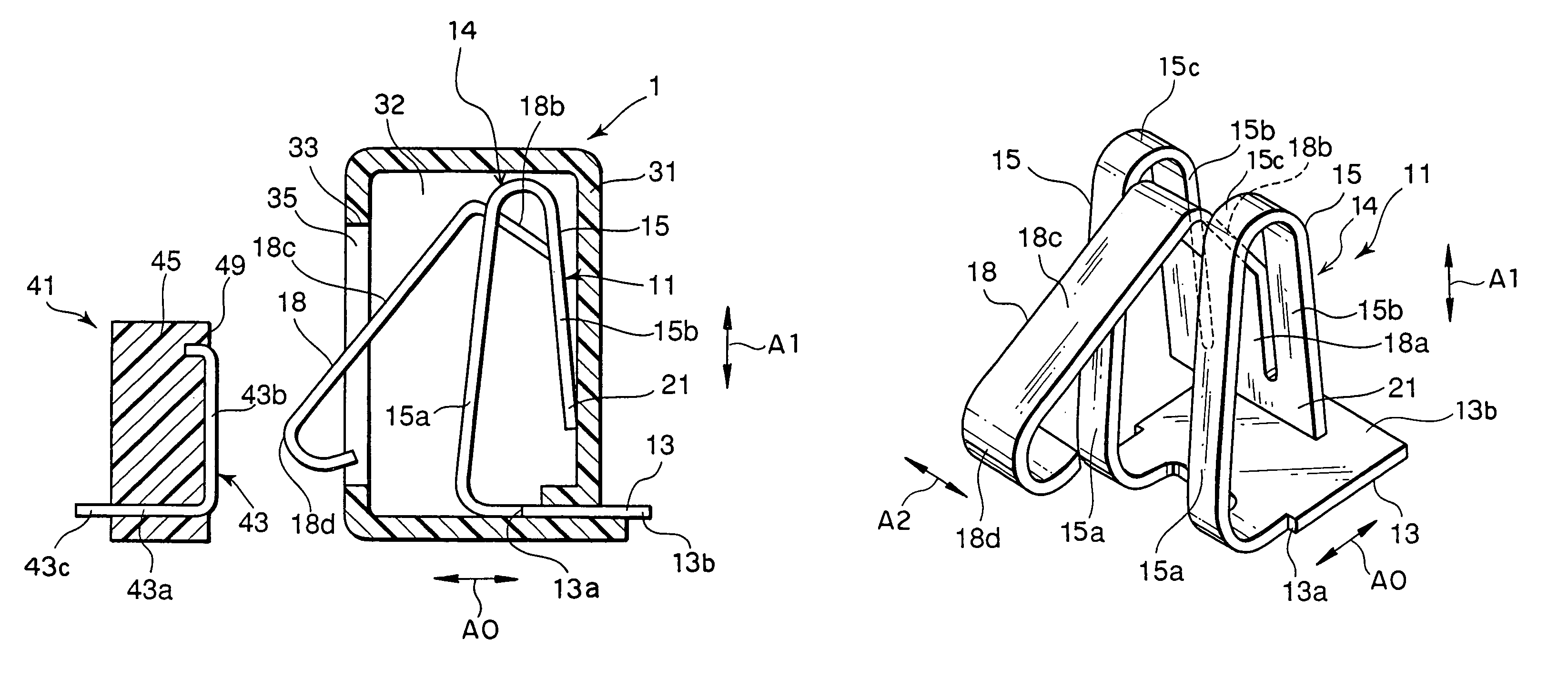
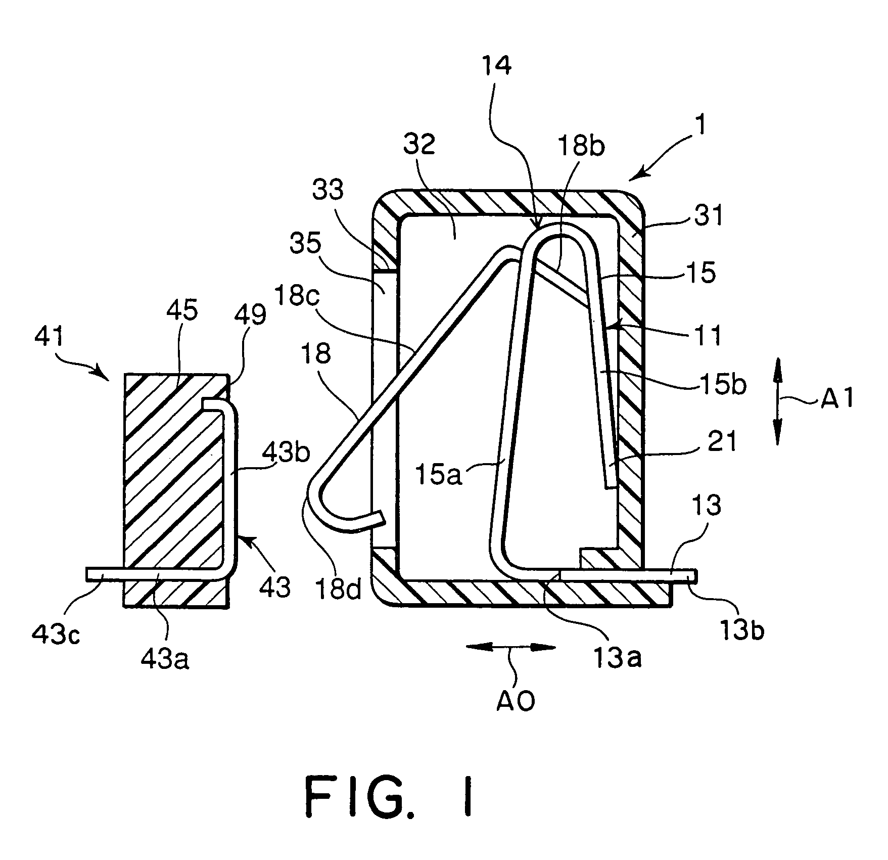
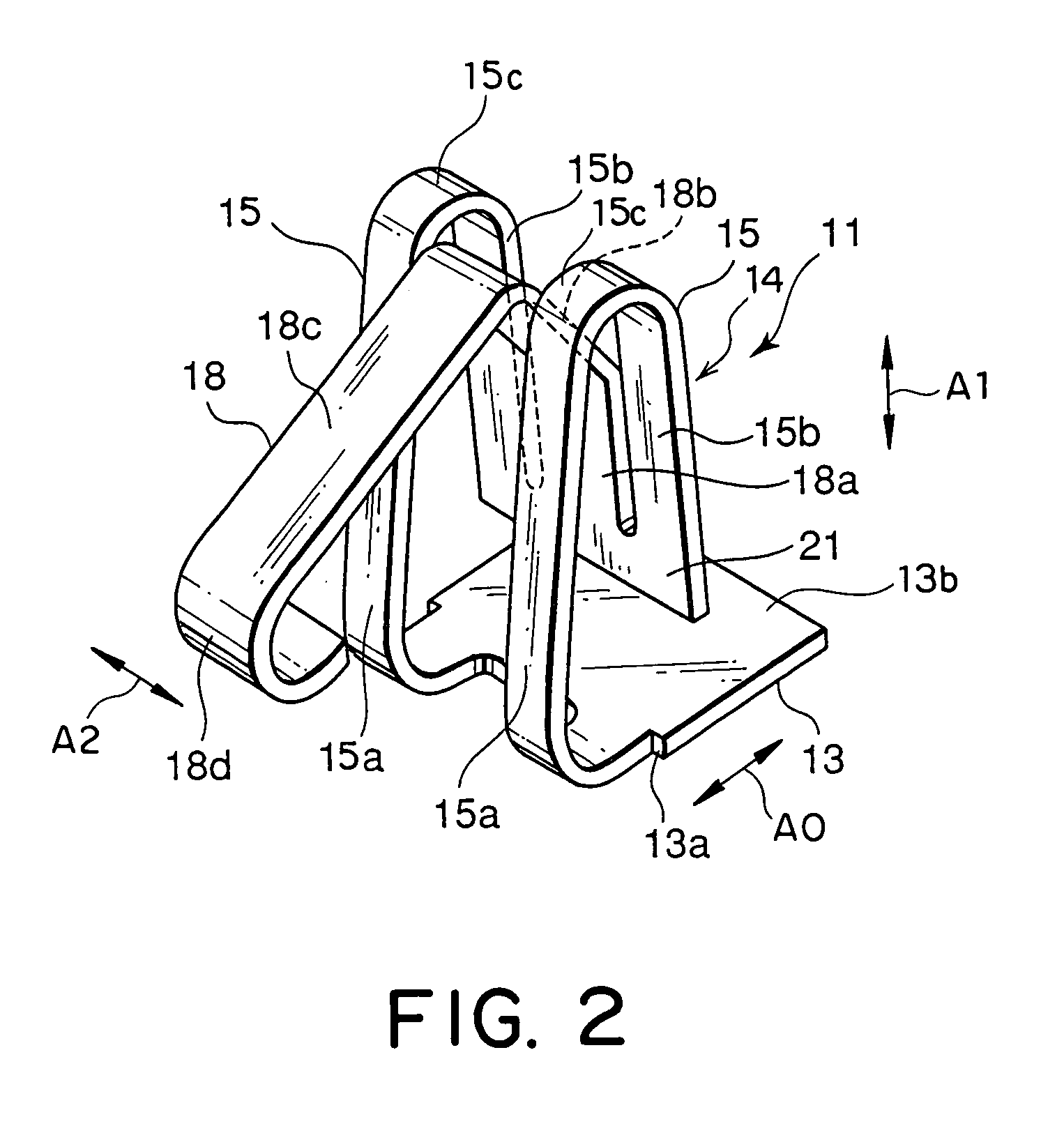
[0012]Referring to FIGS. 1 and 2, description will be made as regards an electrical connector according to an embodiment of this invention.

[0013]The electrical connector in the figures is depicted by a reference numeral 1 and is adapted to be connected with a mating connector 41 in a predetermined direction A0. The mating connector 41 comprises a mating insulator 45 of a plastic material and a mating contact 43 coupled to the mating insulator 45. The mating contact 43 has conductivity and has a mating base portion 43a molded in and fixed to the mating insulator 45, a mating contact portion 43b extending along a principal surface 49, and a mating terminal portion 43c to be connected with a mating circuit board or a cable of a battery charger by soldering.

[0014]The electrical connector 1 comprises a conductive contact 11 and an insulator 31 holding the contact 11 by a molding technique. The insulator 31 is made of a plastic material and defines an accommodating space 32. The insulator...


PUM


Abstract

In an electrical connector to be connected to a mating connector in a predetermined direction, an insulator defines an accommodating space and an opening communicating the accommodating space in the predetermined direction. A contact as a base portion held by the insulator and a spring portion connected to the base portion. The spring portion has a first portion extending from the base portion in the accommodating space to intersect with the predetermined direction, a second portion turned opposite to the opening from the first portion and extending in the accommodating space to intersect with the predetermined direction, and a third portion extending from the second portion to pass through the opening. The third portion has a contact portion located outside the accommodating space to be elastically contacted with the mating connector.

Description

[0001]This application claims priority to prior Japanese patent application JP 2004-171062, the disclosure of which is incorporated herein by reference.BACKGROUND OF THE INVENTION[0002]The present invention relates to an electrical connector to be connected to a mating electrical connector and, in particular, to an electrical connector having a wiping function known in the art.[0003]For example, an electrical connector of the type is disclosed in Japanese Unexamined Patent Application Publication (JP-A) No. H11-074014 (Reference 1). The electrical connector comprises a contact and a housing holding the contact. The contact includes a fixing part fixed to the housing, a spring part extending in an inner space of the housing, and a contact part connected to the spring part and exposed out of the housing. The spring part is bent at a sharp angle from the fixing part to extend in a first direction and is turned to extend in a second direction opposite to the first direction. Namely, the...

Claims


Application Information

Patent Timeline
Patent Type & Authority Patents(United States)
IPC IPC(8): H01R12/00H01R13/24H01R13/62
CPCH01R13/2442
Inventor MATSUNAGA, AKIHIROSHIMADA, MASAAKINATORI, AKIRASUZUKI, KEIICHIRO
Owner JAPAN AVIATION ELECTRONICS IND LTD
Learn More