Electronically controlled prosthetic system

a technology of electromechanical control and prosthetic feet, applied in the field of electromechanical control of prosthetic feet, can solve the problems of insufficient biomechanical characteristics of current mechanically designed prosthetic feet, inability to achieve significant alterations in gait speed without losing optimal biomechanical characteristics, and deficiency in prior art on numerous levels, so as to improve safety, optimize energy return, and improve the effect of uneven ground

Inactive Publication Date: 2006-04-18
MARTIN JAMES JAY
View PDF9 Cites 203 Cited by
  • Summary
  • Abstract
  • Description
  • Claims
  • Application Information

AI Technical Summary

Benefits of technology

[0022]It is therefore an object of the present invention to provide a new and improved prosthetic joint system, and more particularly, a prosthetic ankle and foot system that provides greater ease, safety, and function to a wide range of activities such as but not limited to moving from a walk to a run, transverse from flat ground to an up hill grade, or transverse from flat ground to a down hill grade.
[0033]Still further, an object of the present invention is to provide a new and improved prosthetic joint system wherein instantaneous communication from the user to the prosthesis is achieved for better regulating, controlling, or positioning the prosthesis.

Problems solved by technology

Although, it is known in the art to manufacture ankle and foot prosthetic combinations that have generally increased performance and appearance, the prior art is still deficient on numerous levels as will be discussed in greater detail below.
Typically, models aligned for such activities as daily walking are not optimally aligned for running and vise versa.
Furthermore, while prior art prosthetic devices may have generally moved amputees toward more biomechanically appropriate gait patterns, current mechanically designed prosthetic feet do not allow for significant alterations in gait speed without losing optimal biomechanical characteristics essential with walking or running.
Unfortunately, neither provides both optimal energy return and uneven ground accommodation sufficiently to meet user needs.
Another consideration lacking in the prior art of ankle and foot devices is the combination of aesthetics and function.
A common complaint of many prosthetic foot users is that their prosthetic foot “sticks up” when they sit.
This remains a problem due to the prior art prosthetic feet being affixed at a given angle with respect to the prosthesis, thus, during sitting the foot remains pointing upwards as the shin section of the prosthesis has a posterior lean when the amputee is sitting.
Furthermore, the stubbing of a prosthetic foot has proven to be a safety issue for trans-tibial, trans-femoral, and hip-disarticulation amputees alike at all activity levels.
The prior art prosthetic feet have attempted to dorsiflex the foot during swing phase in the past, such as with the a prior art design under the trademark or name HYDROCADANCE, but have generally failed to provide the full range of benefits desired, such as being able to be used on a vast array of lower extremity amputees' functional abilities and amputation levels as well as provide optimal energy return characteristics, range of motion, and a life-like appearance, to name a few.
Although prosthetic technology has advanced in recent years, the prior art still has failed to bridge the gap between man made prosthetics and user demand and needs.

Method used


Image

  • Electronically controlled prosthetic system
  • Electronically controlled prosthetic system
  • Electronically controlled prosthetic system

Examples


Embodiment Construction

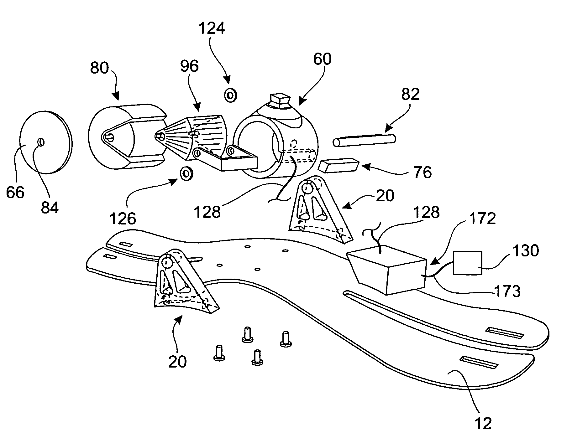
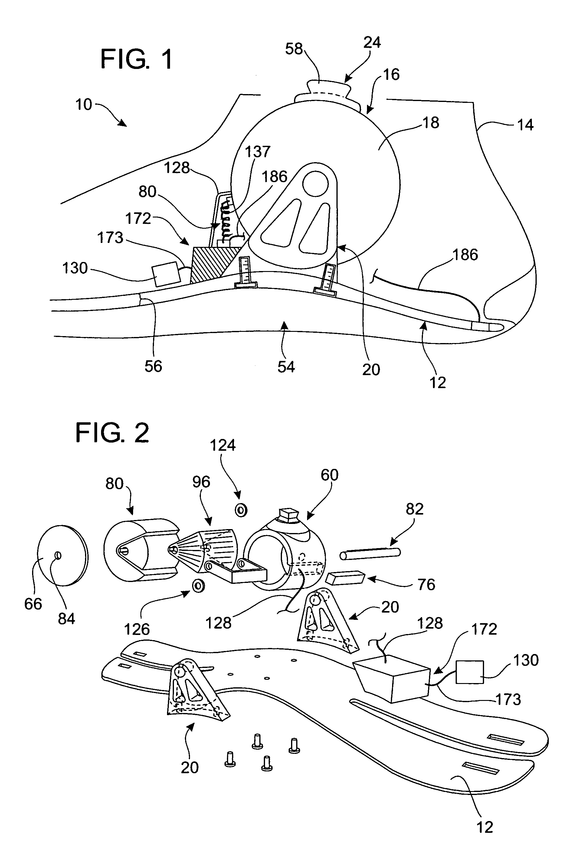
[0074]Referring now to the drawings, wherein like reference numerals designate corresponding structure throughout the views, and referring in particular to FIGS. 1 and 2, reference numeral 10 generally refers to a new and improved prosthetic foot with ankle system, hereinafter referred to as prosthetic foot collectively, in accordance with the present invention. Invention 10 generally comprises keel 12, foot shell 14, ankle joint assembly 16, dampening means or system 18, a bracket assembly 20, sensor system 22, and attachment means 24.

[0075]Furthermore, invention 10 is generally shown in a configuration for a right foot. It is understood that a left foot configuration is considered. It is further understood that invention 10 may be used on other joints and associated appendages. The term appendages should not be considered limited to limbs such as arms and legs. Still furthermore, the term joint generally refers to rotationally attached members.

Keel

[0076]Referring to the drawings a...


PUM


Abstract

A prosthetic joint system for users comprising a housing having an interior cavity, a center axis in said interior cavity, and an attachment means for fixedly connecting said housing to said user; an inner cylinder disposed in said housing interior cavity wherein said inner cylinder rotates around said center axis of said housing; an appendage attached to said inner cylinder; a sensor system attached to said appendage; and a dampening system, having a power source, in communication with said sensor system, said inner cylinder, and said housing for controlling dampening of the rotation of said inner cylinder around said center axis of said housing.

Description

CROSS-REFERENCE TO RELATED APPLICATIONS[0001]Priority is claimed from provisional patent application U.S. Ser. No. 60 / 371,974, filed on Apr. 12, 2002, and incorporated by reference herein.FIELD OF THE INVENTION[0002]The present invention relates generally to an ankle and foot joint system. More particularly, the present invention is a new and improved prosthetic joint system which simulates natural human locomotion and human biomechanics through sensory feed back, time feedback, electronically controlled dampening joint assembly, and a microprocessor control system.DESCRIPTION OF THE KNOWN PRIOR ART[0003]As the study of human physiology and anatomy clearly demonstrates, the relative simple action of walking on an even flat surface involves numerous biomechanical complexities. A single step requires constant biofeedback such as continual analysis of proprioception, angulations, timing, and balanced muscular-skeletal functions. In the prior art, the prosthetic industry is continuously...

Claims


Application Information

Patent Timeline
Patent Type & Authority Patents(United States)
IPC IPC(8): A61F2/66A61F2/48A61F2/00A61F2/50A61F2/58A61F2/60A61F2/64A61F2/68A61F2/70A61F2/72A61F2/76
CPCA61F2/6607A61F2/68A61F2/581A61F2250/008A61F2/585A61F2/605A61F2/64A61F2/72A61F2002/5001A61F2002/5003A61F2002/5004A61F2002/5018A61F2002/5021A61F2002/503A61F2002/5032A61F2002/5033A61F2002/5041A61F2002/5043A61F2002/6621A61F2002/6642A61F2002/6685A61F2002/6818A61F2002/6854A61F2002/6863A61F2002/701A61F2002/704A61F2002/705A61F2002/7635A61F2002/7655A61F2/582A61F2/70
Inventor MARTIN, JAMES JAY
Owner MARTIN JAMES JAY
Why Eureka
Try Eureka