

Plated material and method of manufacturing the same, terminal member for connector, and connector
a technology of plated materials and terminal parts, which is applied in the direction of single bars/rods/wires/strips conductors, coupling device connections, other domestic articles, etc., can solve the problems of increasing the insertion force (and withdrawal force) of the connector, the need to take into account the fatigue of workers, and the increase of the demand for multi-pin connectors. , to achieve the effect of enhancing sliding and reducing electrical resistan
Active Publication Date: 2006-04-18
MITSUBISHI SHINDOH CO LTD
View PDF14 Cites 21 Cited by
- Summary
- Abstract
- Description
- Claims
- Application Information
AI Technical Summary
Benefits of technology
The present invention relates to a plated material that has a soft region and a hard region in a network-shaped pattern on its surface. The soft region has a lower hardness and the hard region has a higher hardness. The soft region can be located at a higher position on the surface of the substrate. The plated material can be used for connector applications and can enhance slidability and prevent excess wear. The substrate can be made of a copper alloy with specific elements and can be formed by various methods such as segregation or oxidation. The plated material has a low cost of manufacture.
Problems solved by technology
As multi-functionalization has recently progressed, electric and electronic circuits have become complicated and multipolarization of connectors used therein has advanced, and thus demands for multi-pin connectors have increased.
With the spread of multi-pin connectors, insertion force (and withdrawal force) of the connectors tend to increase and it becomes necessary to take worker fatigue into consideration.
However, in a conventional terminal made of a Sn plated Cu alloy sheet, since both a male terminal and a female terminal have a relatively soft surface, sliding resistance between terminals was relatively large.
Therefore, there was a limit to the reduction in the insertion and withdrawal forces.
Method used
View moreImage
Smart ImageViewing Examples

Examples
examples
[0067]The following Examples further illustrate the present invention in detail.
Login to View More PUM
| Property | Measurement | Unit |
|---|---|---|
| size | aaaaa | aaaaa |
| thickness | aaaaa | aaaaa |
| thickness | aaaaa | aaaaa |
Abstract
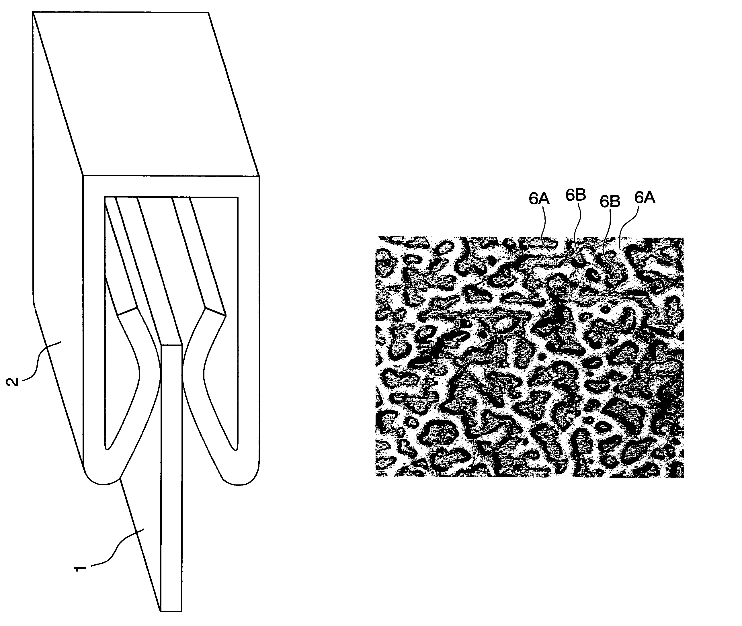
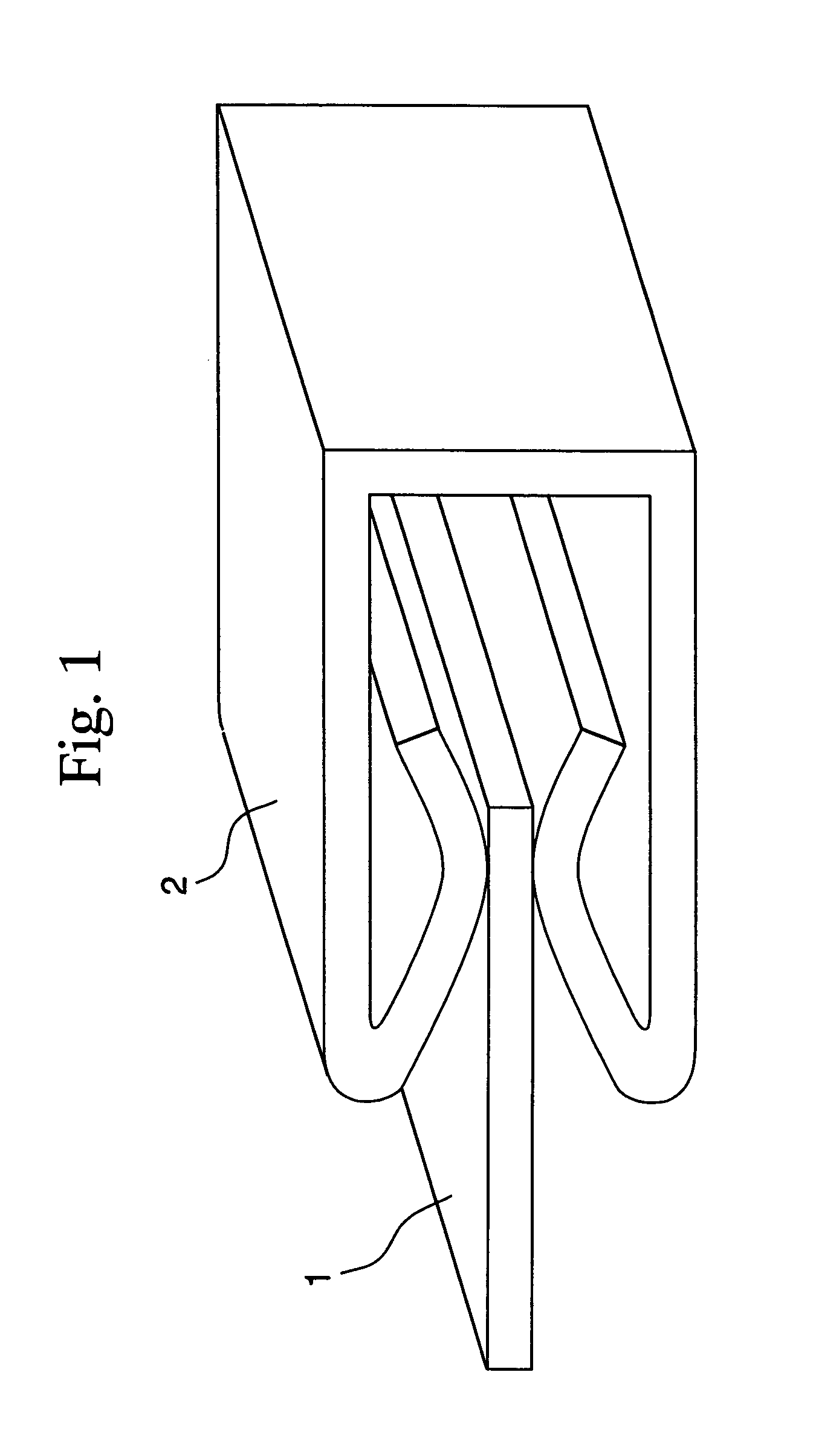
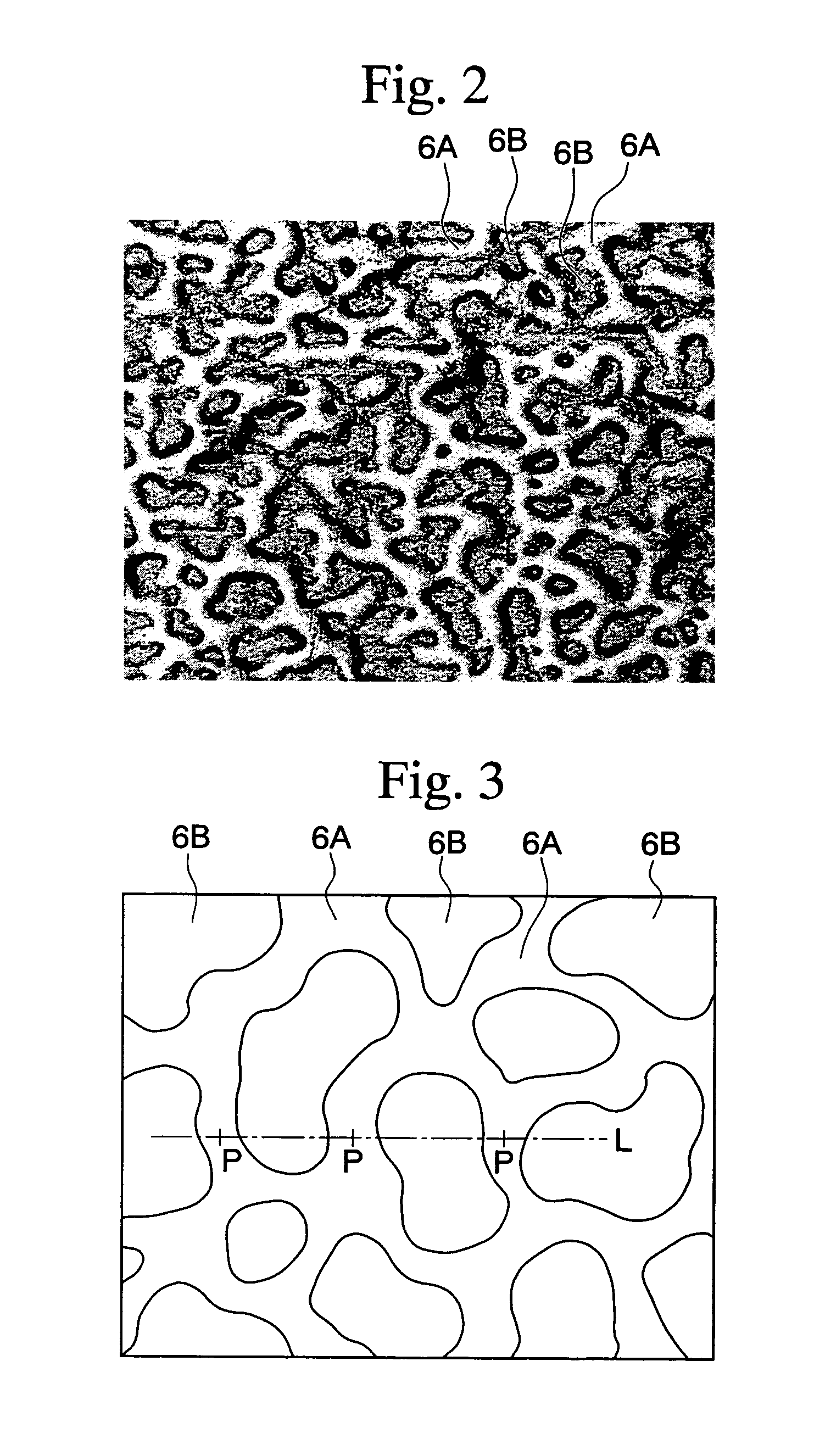
A plated material reduces insertion and withdrawal forces when used in a connector. A terminal member for a connector and a connector therewith are also provided. The plated material comprises a substrate 3 made of Cu or a Cu alloy and a metal plating layer 6 formed on the surface of the substrate 3. A soft region 6A spreading in a network-shape and a hard region 6B surrounded by the network of the soft region 6A coexists in the metal plating layer 6. The soft region 6A has a Vickers hardness of 20 to 250, while the hard region 6B has a Vickers hardness of 60 to 700, which is at least 30 higher than that of the soft region 6A. An average size of the network of the soft region 6A is from 5 to 500 μm.
Description
BACKGROUND OF THE INVENTION[0001]1. Field of the Invention[0002]The present invention relates to a plated material and to a method of manufacturing the same, to a terminal member for a connector, and to a connector.[0003]2. Description of Related Art[0004]Terminals of such as connectors for electrical wiring used in automobiles are manufactured by press working, blanking or bending of a copper alloy sheet. To enhance electrical connection characteristics of the resulting terminals, the copper alloy sheet is often subjected to Sn or Sn alloy plating. For example, Japanese Patent Application, First Publication No. Hei 7-268511 discloses an example of such terminals.[0005]As multi-functionalization has recently progressed, electric and electronic circuits have become complicated and multipolarization of connectors used therein has advanced, and thus demands for multi-pin connectors have increased. For example, the automobile assembling process includes numerous processes for mounting c...
Claims
Login to View More Application Information
Patent Timeline
 Patent Type & AuthorityPatents(United States)
IPC IPC(8): B32B15/00C25D5/50H01H1/02H01H1/38B32B15/01C25D7/00C22C9/00C22C9/04C22C13/00C25D3/30C25D5/10C25D5/34H01B5/02
CPCB32B15/017H01R13/03Y10S428/929Y10T428/12715Y10T428/12389Y10T428/12993Y10S428/941C25D3/30
InventorMORI, AKIHITOSUZUKI, TAKESHISAKAKIBARA, TADAOUMEZU, SHUZOISHIDA, MASAHIKO
OwnerMITSUBISHI SHINDOH CO LTD