Electron beam apparatus having electron analyzer and method of controlling lenses

an electron analyzer and electron beam technology, applied in the field of electron beam apparatuses, can solve the problems of unsatisfactory accuracy compared with energy resolution, inconvenient operation, and inability to accurately measure the intensity of the beam,

an electron analyzer and electron beam technology, applied in the field of electron beam apparatuses, can solve the problems of unsatisfactory accuracy compared with energy resolution, inconvenient operation, and inability to accurately measure the intensity of the beam,

US7030389B2Active Publication Date: 2006-04-18JEOL LTD

Image

  • Electron beam apparatus having electron analyzer and method of controlling lenses
  • Electron beam apparatus having electron analyzer and method of controlling lenses
  • Electron beam apparatus having electron analyzer and method of controlling lenses

Examples


Embodiment Construction

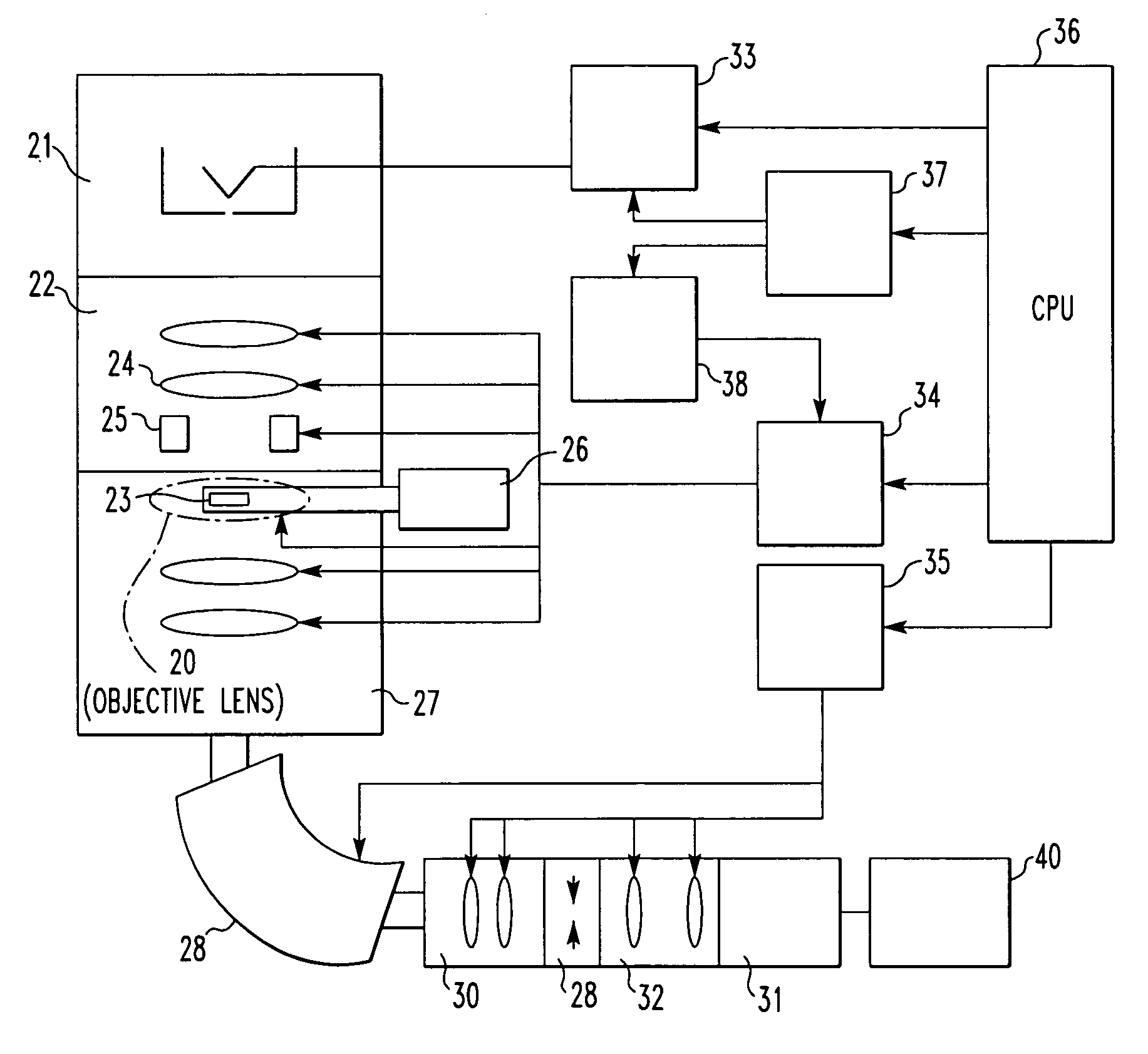
[0045]Embodiments of the present invention are hereinafter described in detail with reference to the accompanying drawings. FIG. 8 shows a transmission electron microscope according to the present invention. This microscope has an electron gun 21 producing and accelerating an electron beam. The beam is condensed by an illumination optical system 22 and illuminated at a specimen 23. The illumination optical system 22 includes plural condenser lenses 24 and deflection coils 25 for axial correction. The specimen 23 is held in a specimen holder 26 mounted to a specimen stage (not shown).

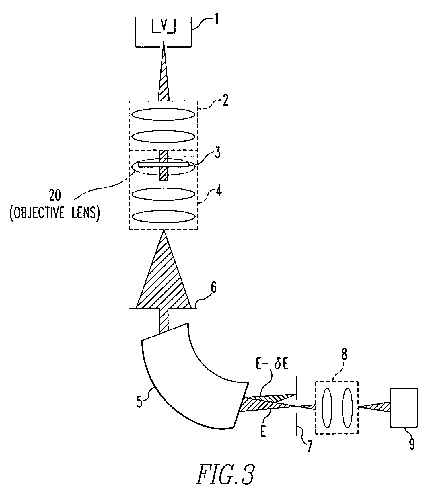
[0046]An imaging optical system 27 for imaging a TEM image is mounted behind the specimen holder 26 and fitted with plural lenses and plural deflection coils. An electron energy analyzer 28 is mounted behind the imaging optical system 27. In the present embodiment, a sector-shaped magnetic field is used as the analyzer. Incident electrons are dispersed within the analyzer according to their energies. An ...


PUM

PropertyMeasurementUnit
energy shiftaaaaaaaaaa
electron beamaaaaaaaaaa
magnetic fieldaaaaaaaaaa

Abstract

An electron beam apparatus having an electron analyzer is achieved which can control the illumination lens system by feedback without adversely affecting the imaging action even if a specimen is positioned within the magnetic field of the objective lens. The apparatus has an energy shift control module for controlling energy shift. On receiving instructions about setting of energy shift from the CPU, the control module issues an instruction for shifting the accelerating voltage to a specified value to an accelerating-voltage control module. The control module also sends information about the energy shift to an energy shift feedback control module, which calculates the feedback value and supplies information about corrections of lenses and deflection coils to a TEM optics control module. The feedback value is multiplied by a corrective coefficient that can be calibrated.

Description

BACKGROUND OF THE INVENTION[0001]1. Field of the Invention[0002]The present invention relates to an electron beam apparatus for focusing an electron beam onto a specimen with condenser lenses and an objective lens to image electrons transmitted through the specimen and, more particularly, to an electron beam apparatus which has an electron analyzer and acts to image only electrons having an energy coincident with the characteristic absorption energy of a certain element transmitted through the specimen.[0003]2. Description of Related Art[0004]Electron microscopes are roughly classified into two types: transmission electron microscope and scanning electron microscope. In a transmission electron microscope, an electron beam produced and accelerated from an electron gun is focused onto a specimen by condenser lenses and an objective lens. Electrons transmitted through the specimen or scattered electrons are imaged onto a fluorescent screen, photographic film, or TV camera.[0005]Sometim...

Claims


Application Information

Patent Timeline
18 Apr 2006
Publication
US7030389B2
IPC
G01K1/08; G01N23/00; G21K7/00; H01J37/26; H01J37/05; H01J37/24; H01J37/244
CPC
H01J37/05; H01J37/241; H01J37/265; H01J37/244; H01J2237/24485
Inventors
KANEYAMA, TOSHIKATSU