Permanent magnet element and electric machine

a permanent magnet and electric machine technology, applied in the direction of magnetic body, magnetic circuit rotating parts, magnetic circuit shape/form/construction, etc., can solve the problems of slowing down the final completion of the device, difficult to get the piece into the oven, and small size of the permanent magnet pieces

Inactive Publication Date: 2006-04-18
ABB TECH AG
View PDF16 Cites 29 Cited by
  • Summary
  • Abstract
  • Description
  • Claims
  • Application Information

AI Technical Summary

Benefits of technology

[0005]It is an object of the present invention to provide a permanent magnet element that avoids the above-mentioned drawbacks and enables permanent magnets to be mounted on an electric device in a simpler manner than before. This object is achieved by a permanent magnet element of the invention which is characterized in that the permanent magnet element also comprises a protective cover that is arranged to partly surround the permanent magnet pieces arranged in the element, and that the permanent magnet element also comprises one or more fastening elements.

Problems solved by technology

A problem with the present permanent magnets used in electrotechnical devices is the difficult fastening and small size of the permanent magnet pieces.
Especially the resin-hardening phase is long and slows down the final completion of the device.
In addition, getting the piece into an oven is hard to accomplish, if the piece, for instance the rotor, is large.
The band does not, however, provide a sideways support for the magnets.
In addition, when mounting permanent magnets or permanent magnet elements, external magnetic metal pieces fasten strongly to their surfaces and hamper and slow the mounting.

Method used


Image

  • Permanent magnet element and electric machine
  • Permanent magnet element and electric machine
  • Permanent magnet element and electric machine

Examples


Embodiment Construction

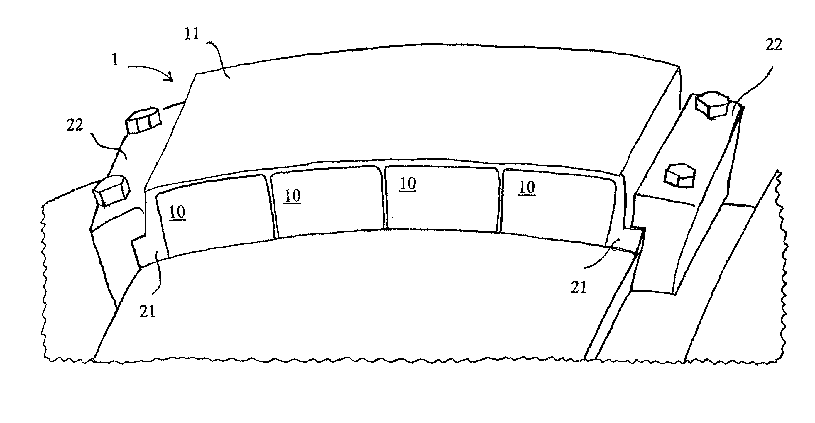
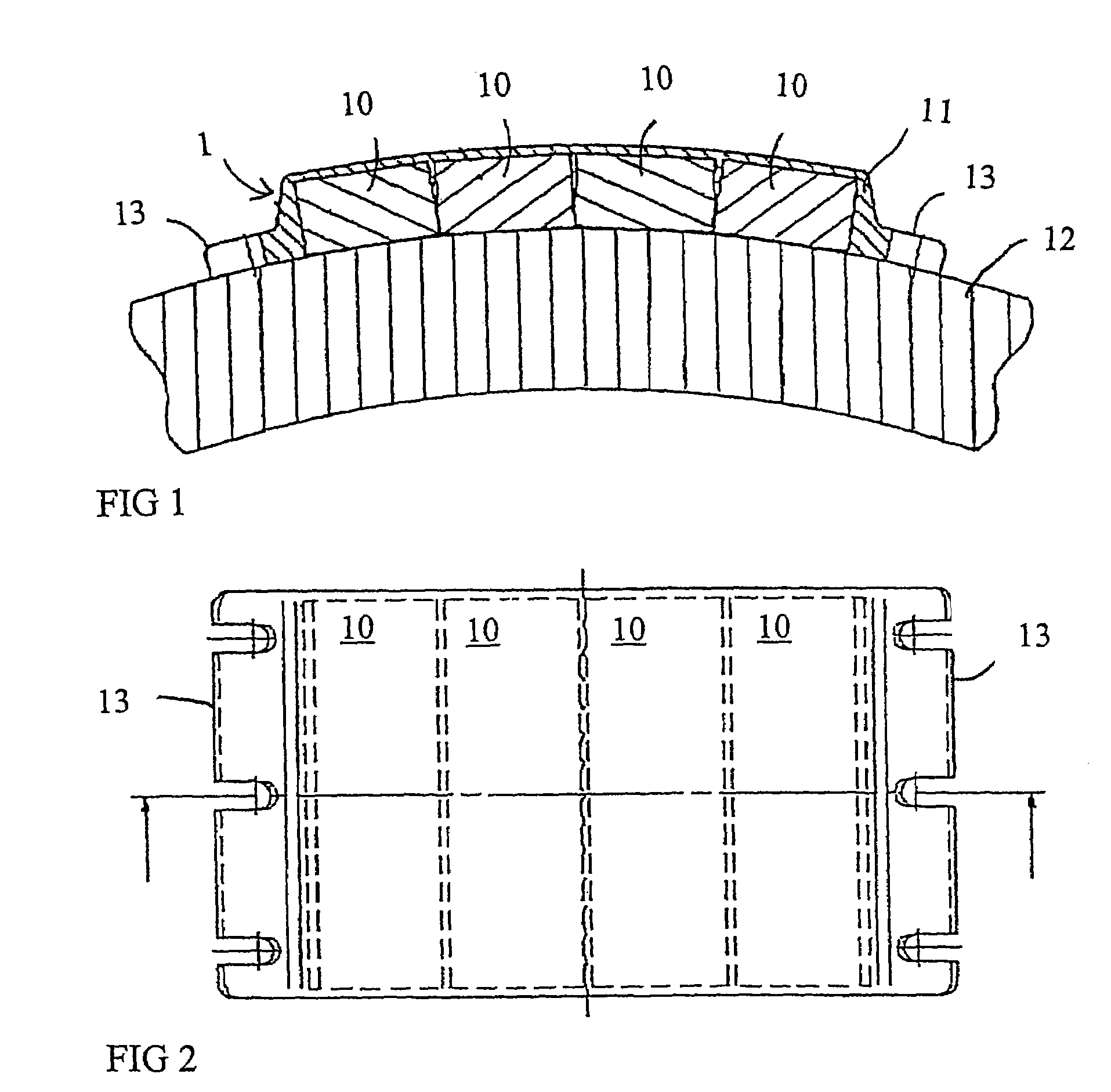
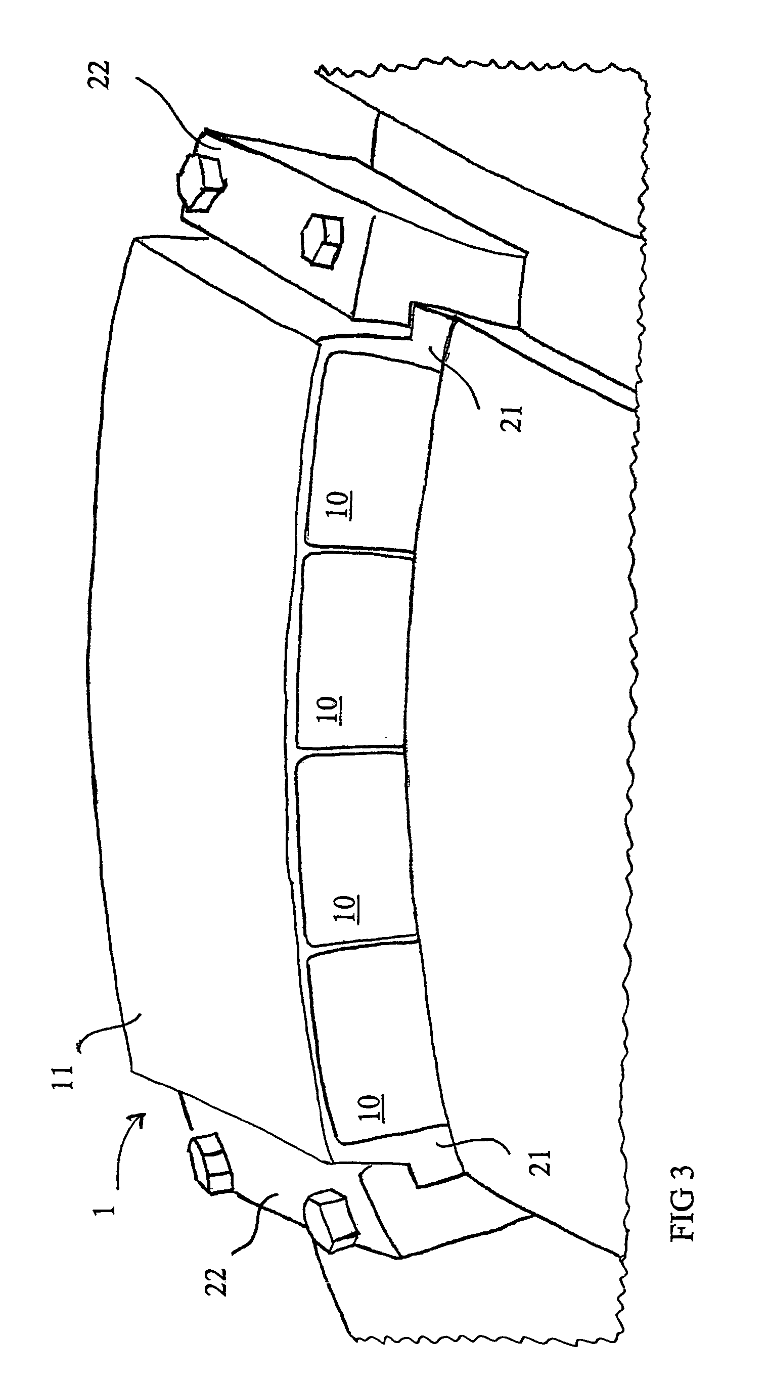
[0015]FIGS. 1 and 2 show the structure of an embodiment of the permanent magnet element 1 of the invention. FIG. 1 is a cross-section of the structure of FIG. 2, in which the permanent magnet element 1 is shown from the top. The element of the invention comprises at least one permanent magnet piece 10. In the examples of FIGS. 1 and 2, there are 4 of these pieces 10.

[0016]According to the invention, the permanent magnet element 1 further comprises a protective cover 11 that is arranged to partly surround the permanent magnet pieces in the element or the sole permanent magnet piece of the element. The protective cover 11 is preferably also made in such a manner that the pieces in the element fasten reliably with respect to each other, whereby the structure of the element becomes uniform and strong.

[0017]The element shown in the figures is fastened to an electrotechnical device that in the embodiments of the figures is the rotor 12 of an electric machine of the invention, which is to ...


PUM

PropertyMeasurementUnit
shapeaaaaaaaaaa
magnetizationaaaaaaaaaa
non-magneticaaaaaaaaaa

Abstract

A permanent magnet element intended especially for electrotechnical devices and an electric machine, the element (1) comprising at least one permanent magnet piece (10). The permanent magnet element (1) also comprises a protective cover (11) that is arranged to partly surround the permanent magnet pieces (10) arranged in the element, and the permanent magnet element (1) also comprises one or more fastening elements (13; 21).

Description

BACKGROUND OF THE INVENTION[0001]The present invention relates to a permanent magnet element intended especially for electrotechnical devices, the element comprising at least one permanent magnet piece. The invention also relates to an electric machine as described in the preamble of claim 11.[0002]Permanent magnets are generally used in electric machines for generating magnetic fields and further for utilizing the interaction between a magnet field and conductor in rotating electric machines. An example of a rotating electric machine is a permanently magnetized synchronous machine having permanent magnets mounted on its rotor and a three-phase winding typically mounted on its stator. When the rotor turns, the rotating magnetic flux generated by the magnets in the rotor crosses the stator windings and generates current in the stator coils. Correspondingly, when alternating current is fed into the stator, a magnetic flux is generated in the stator coils that when rotating turns the p...

Claims


Application Information

Patent Timeline
Patent Type & Authority Patents(United States)
IPC IPC(8): H02K1/28H02K1/18H02K1/30H01F7/02H02K1/27
CPCH02K1/278H01F7/0221
Inventor MALMBERG, JUKKA
Owner ABB TECH AG
Why Eureka
Try Eureka