Method for setting a termination voltage and an input circuit
a technology of input circuit and termination voltage, which is applied in the direction of pulse technique, dc level restoring means or bias distortion correction, instruments, etc., can solve the problems that the deviation of individual termination voltages cannot be compensated by changing the reference voltage, and the reception of signals is sensitive to systematic signal distortion. , to achieve the effect of improving quality
- Summary
- Abstract
- Description
- Claims
- Application Information
AI Technical Summary
Benefits of technology
Problems solved by technology
Method used
Image
Examples
Embodiment Construction
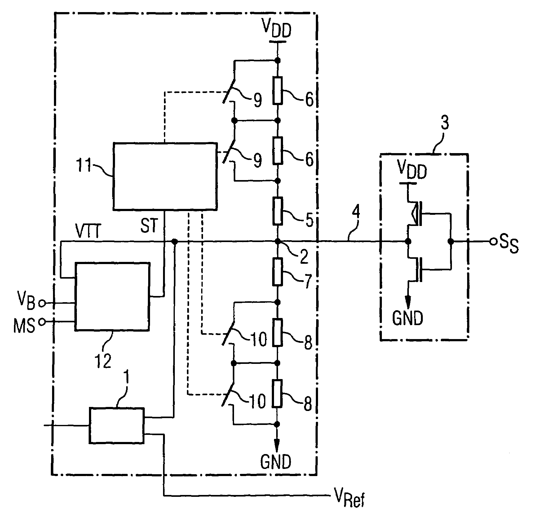
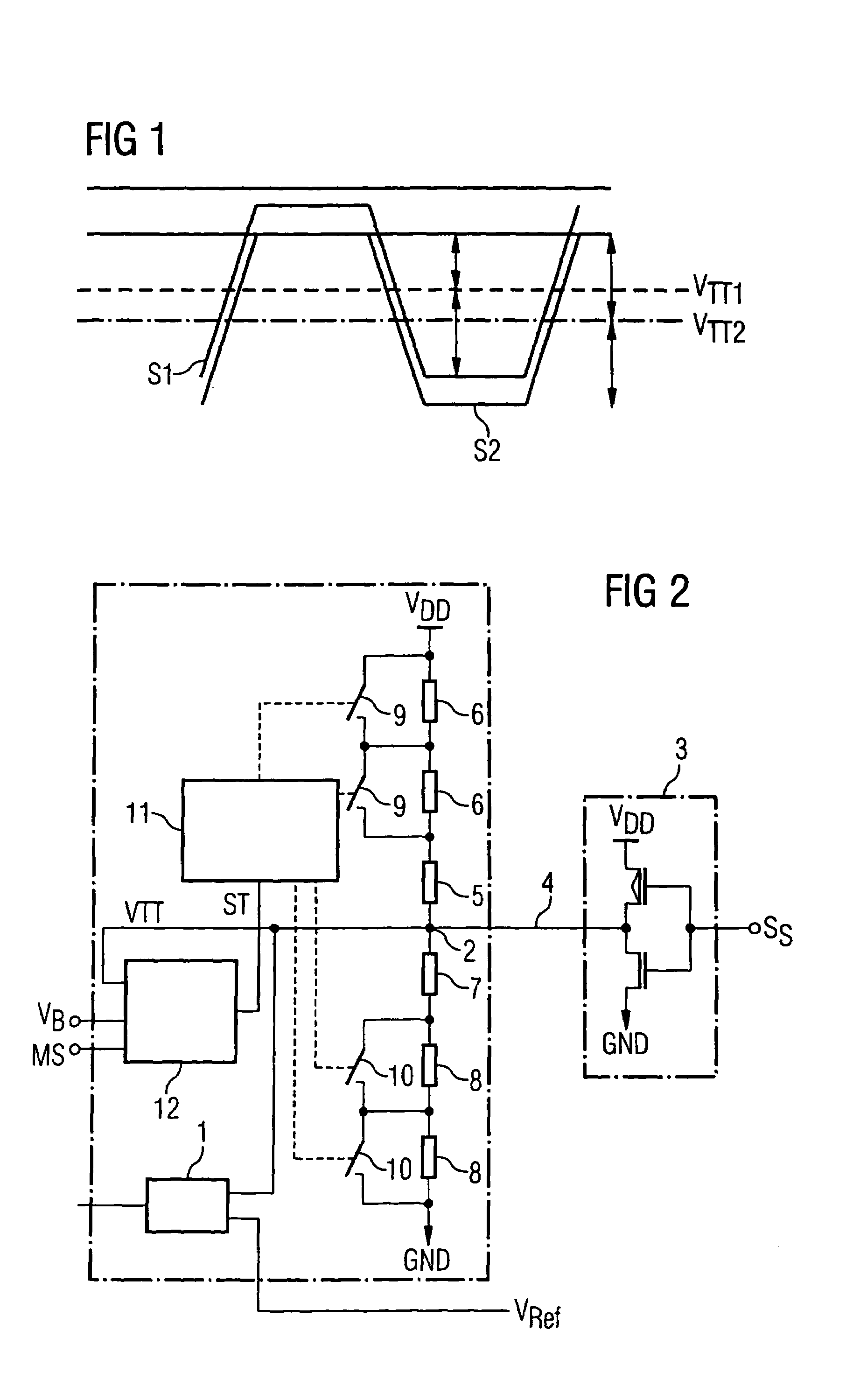
[0021]In the event of a data transfer between a memory controller and a DRAM memory module, the data are transmitted onto a data line with the aid of a driver circuit in the transmission part and received via an input terminal of an input circuit in the reception part. The driver circuit is usually connected in such a way as to pull the voltage level of a termination voltage on the data line, which is provided by the input circuit, to a high potential or a low potential, depending on what signal value is intended to be transmitted. On account of the resistances and inductances of the data line and of the input terminal of the input circuit, the high potential and the low potential made available to the driver circuit are not completely reached.
[0022]In order for the signal levels of the signal to be transferred to vary in a defined manner about a center potential, the input circuit provides the termination voltage which is applied to the data line. The driver circuit then drives the...
PUM
 Abstract
Description
Claims
Application Information
 - R&D
- Intellectual Property
- Life Sciences
- Materials
- Tech Scout
- Unparalleled Data Quality
- Higher Quality Content
- 60% Fewer Hallucinations
Browse by: Latest US Patents, China's latest patents, Technical Efficacy Thesaurus, Application Domain, Technology Topic, Popular Technical Reports.
© 2025 PatSnap. All rights reserved.Legal|Privacy policy|Modern Slavery Act Transparency Statement|Sitemap|About US| Contact US: help@patsnap.com


