Image display screen and image display device
a technology of image display screen and display device, which is applied in the direction of projectors, optics, instruments, etc., can solve the problem of not being able to clearly display the image on the opposite side, and achieve the effect of improving transparency
- Summary
- Abstract
- Description
- Claims
- Application Information
AI Technical Summary
Benefits of technology
Problems solved by technology
Method used
Image

Examples
example 1
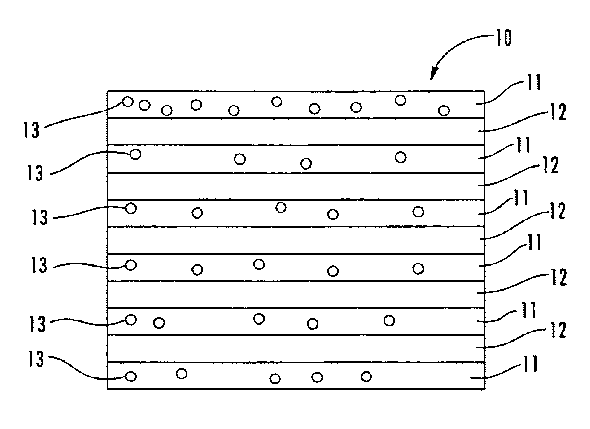
[0076]Polyethylene terephthalate (PET) containing 0.10 wt % of spherical silica particles (average particle diameter: 1.5 μm, long diameter / short diameter ratio: 1.02, average deviation of particle diameter: 0.1) and having an intrinsic viscosity (orthochlorophenol, 35° C.) of 0.63 was prepared as the resin for the first layers and copolyethylene terephthalate containing 10 mol % of isophthalic acid (intrinsic viscosity of 0.68, orthochlorophenol, 35° C.) was prepared as the resin for the second layers.
[0077]After the resin for the first layers was dried at 160° C. for 3 hours and the mixed resin for the second layers was dried at 160° C. for 3 hours, they were supplied into an extruder to be molten, the polymer for the first layers was divided into 101 layers, the polymer for the second layers was divided into 100 layers, a multi-layer feed block device was used to laminate the first layers with the second layers alternately, and the laminated layers were guided into a die and cast...
example 2
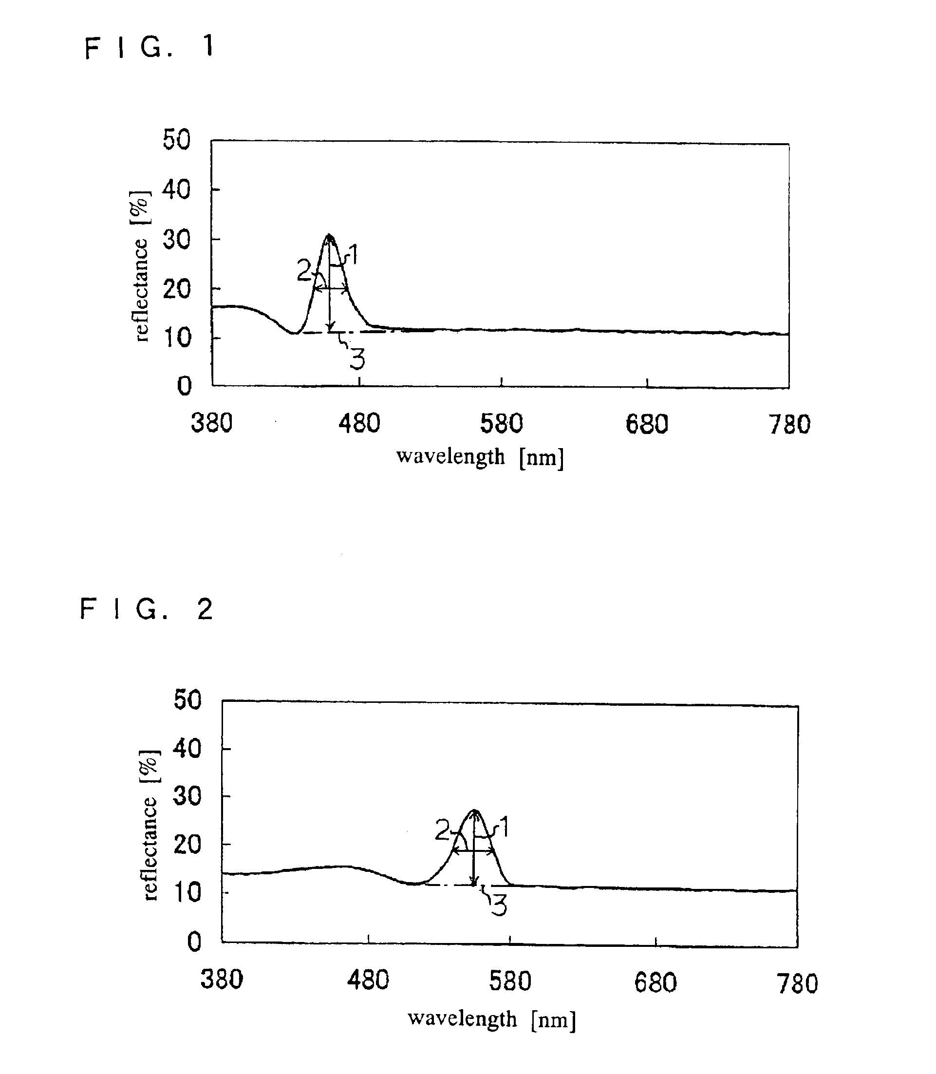
[0080]The procedure of Example 1 was repeated except that the production conditions were changed as shown in Table 1. The characteristic properties of the obtained image display screen are shown in Table 2 and the reflectance for the wavelength of light is shown in FIG. 2.
[0081]When the obtained image display screen was assembled with a 10 mm glass plate using the above pressure-sensitive adhesive sheet and white light (red, green and blue rays) was projected onto the screen on the glass plate by a liquid crystal projector under illumination by a 30-lux fluorescent lamp, a green image could be displayed from the reflection side at a high contrast and a purple image could be displayed from the transmission side at a high contrast. The transparency was extremely high. The characteristic properties of the obtained image display surface are shown in Table 3.
example 3
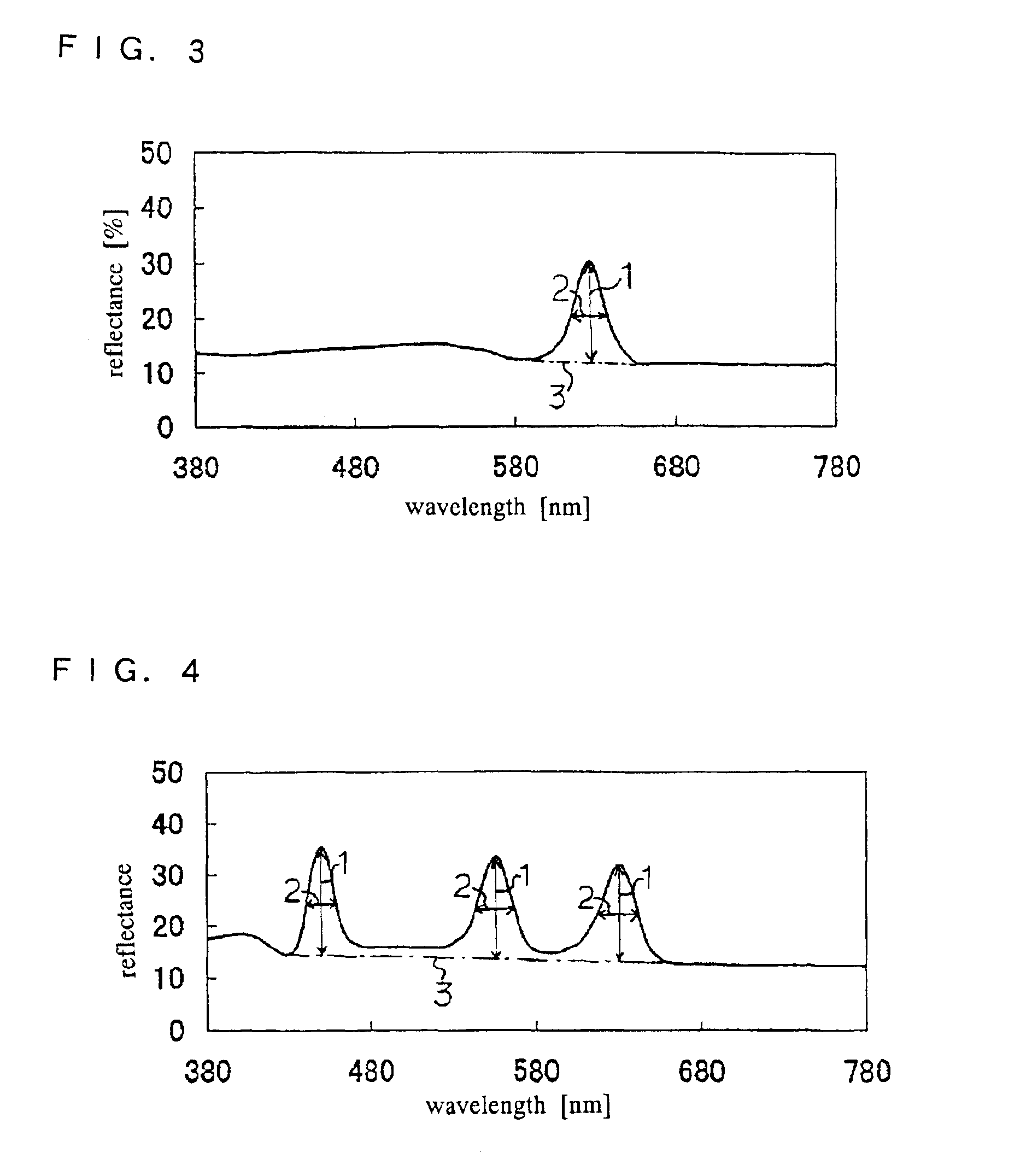
[0082]The procedure of Example 1 was repeated except that the production conditions were changed as shown in Table 1. The characteristic properties of the obtained image display screen are shown in Table 2 and the reflectance for the wavelength of light is shown in FIG. 3.
[0083]When the obtained image display screen was assembled with a 10 mm glass plate using the above pressure-sensitive adhesive sheet and white light (red, green and blue rays) was projected onto the screen on the glass plate by a liquid crystal projector under illumination by a 30-lux fluorescent lamp, a red image could be displayed from the reflection side at a high contrast and a water color image could be displayed from the transmission side at a high contrast. The transparency was extremely high. The characteristic properties of the obtained image display surface are shown in Table 3.
PUM
 Abstract
Description
Claims
Application Information
 - R&D
- Intellectual Property
- Life Sciences
- Materials
- Tech Scout
- Unparalleled Data Quality
- Higher Quality Content
- 60% Fewer Hallucinations
Browse by: Latest US Patents, China's latest patents, Technical Efficacy Thesaurus, Application Domain, Technology Topic, Popular Technical Reports.
© 2025 PatSnap. All rights reserved.Legal|Privacy policy|Modern Slavery Act Transparency Statement|Sitemap|About US| Contact US: help@patsnap.com