Overload current protection apparatus

a protection device and current technology, applied in the direction of emergency protection for supplying operative power, emergency protection arrangements for limiting excess voltage/current, instruments, etc., can solve the problems of low sensitivity of magnetoresistive elements, inability to obtain a wide range of detecting current, and inability to adjust the condition correctly for a long time. , to achieve the effect of preventing magnetic saturation, increasing the range of current detection, and wide applicability

Inactive Publication Date: 2006-04-18
FUJI ELECTRIC FA COMPONENTS & SYST CO LTD
View PDF11 Cites 14 Cited by
  • Summary
  • Abstract
  • Description
  • Claims
  • Application Information

AI Technical Summary

Benefits of technology

[0022]That is, in the present invention, the magnetism detection element having the magnetic impedance (MI) effect is used as the current detection means to prevent magnetic saturation caused by an iron core in a widely used conventional current detection transformer, thereby increasing a range of the current detection. Further, the controlling power-supply source does not need external power supply from a constant-voltage regulated power source. As a result, it is possible to provide an over-current protection device having wide applicability and is capable of decreasing the total cost.
[0023]When a multi-phase AC power-supply source is used, it is not necessary to provide a power-supply transformer for each phase, thereby providing the over-current protection device with a smaller number of parts and low cost. In this case, the oscillating means is a single unit instead of several oscillating means for each phase in the conventional method. It is possible to apply the AC current to the elements and devices disposed for each phase only when selected. Accordingly, it is possible to decrease power consumption. When the power is supplied to the bias coils only upon the detection, it is possible to further reduce the power consumption is further lowered by solely. When the oscillating means is operated only upon the detection, it is possible to further reduce power consumption.
[0024]Further, it is possible to provide only a single system of the holding means and the amplifying means, thereby further reducing power consumption and cost. The positive and negative bias magnetic fields are alternately applied to the magnetism detection element, and a difference in the detected voltages at the time of applying the bias magnetic field is determined. Accordingly, it is possible to improve linearity or the output. Further, a pulse is used to drive intermittently in place of the conventional AC biasing system, thereby further reducing power consumption.
[0025]In addition, the magnetism detection element, AC-current input terminal thereof, bias coil, and current input terminal thereof are integrated with a resin molding process, thereby decreasing the magnetic resistance and bias current and reducing a size. Further, the magnetism detection element, AC-current input terminal thereof, bias coil, current input terminal thereof, and circuit for outputting a signal proportional to the signal output from the magnetism detection element are integrated, thereby improving the S / N (signal-to-noise) ratio. In particular, various corrective data are incorporated in the system to improve the function thereof, thereby obtaining excellent environmental resistance, high precision, and lower power consumption. The thin-film device is used as the magnetism detection element, thereby eliminating the adverse influence of variable output caused by a strain in the wire-type element and reducing power consumption with high precision.

Problems solved by technology

However, in the device using the bi-metal switch, it is difficult to adjust the current in the state that the switch is opened, so that the incorrectly adjusted condition tends to continue for a long time.
However, the electronic device includes a complex circuit, and in order to properly detect a current to operate a contactor, it is necessary to provide a constant-voltage power supply and a large number of components.
Accordingly, it is difficult to obtain a wide range for detecting a current due to magnetic saturation of an iron core.
However, it is necessary to provide an iron core due to a low sensitivity of the magnetoresistive element.
Accordingly, similar to the current detection transformer, it is difficult to obtain a wide range for detecting a current.
Accordingly, it is necessary to apply a high-frequency current of several mA and at least several MHz to the element, thereby increasing the power consumption and a size of the power-supply transformer, and making it difficult to downsize the device and reduce cost of the device.
A current of several mA and a bias current of about several tens of mA are constantly applied to magnetism detection elements 1a, 1b, and 1c, thereby increasing the power consumption in proportion to the number of the elements.

Method used


Image

  • Overload current protection apparatus
  • Overload current protection apparatus
  • Overload current protection apparatus

Examples


first embodiment

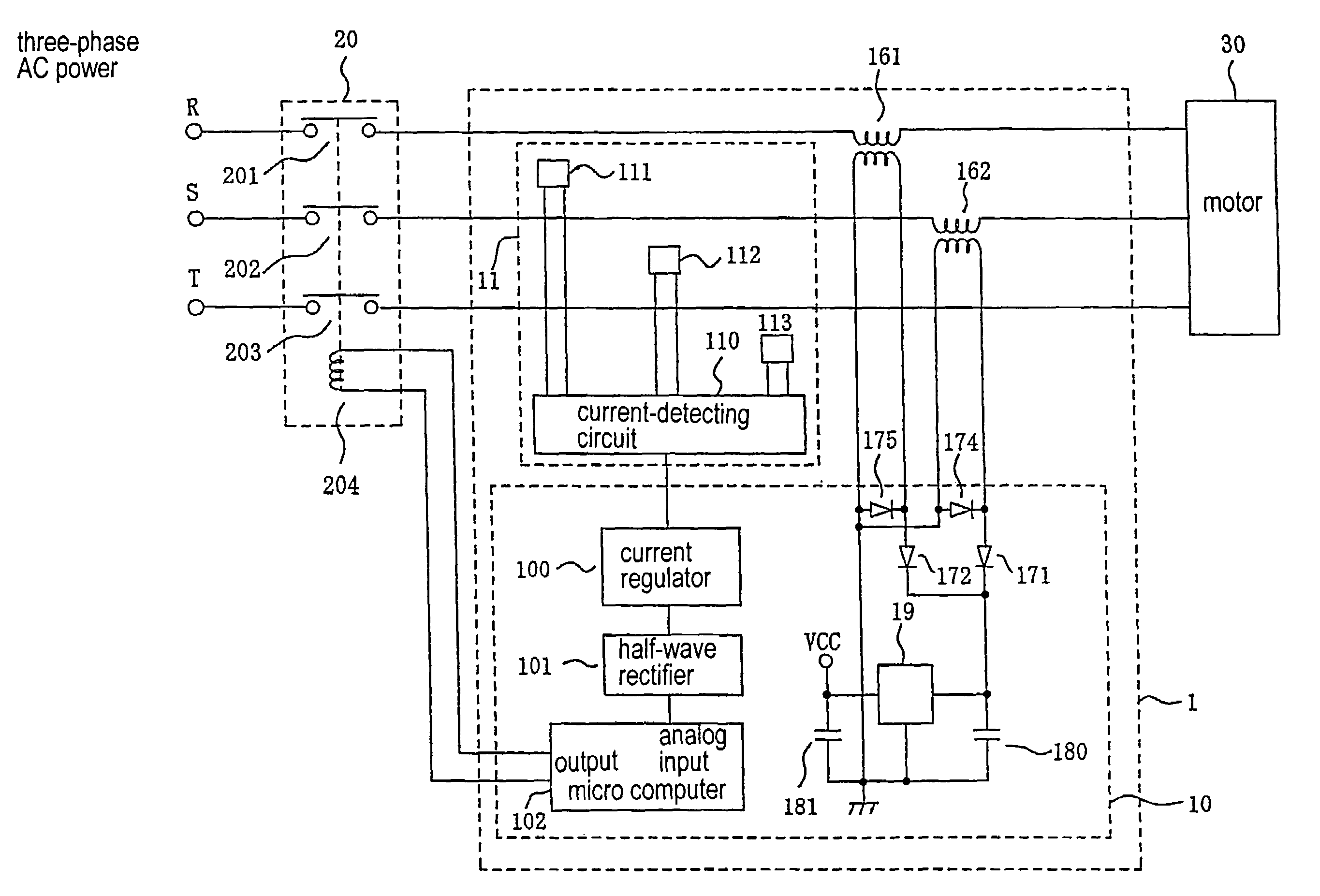
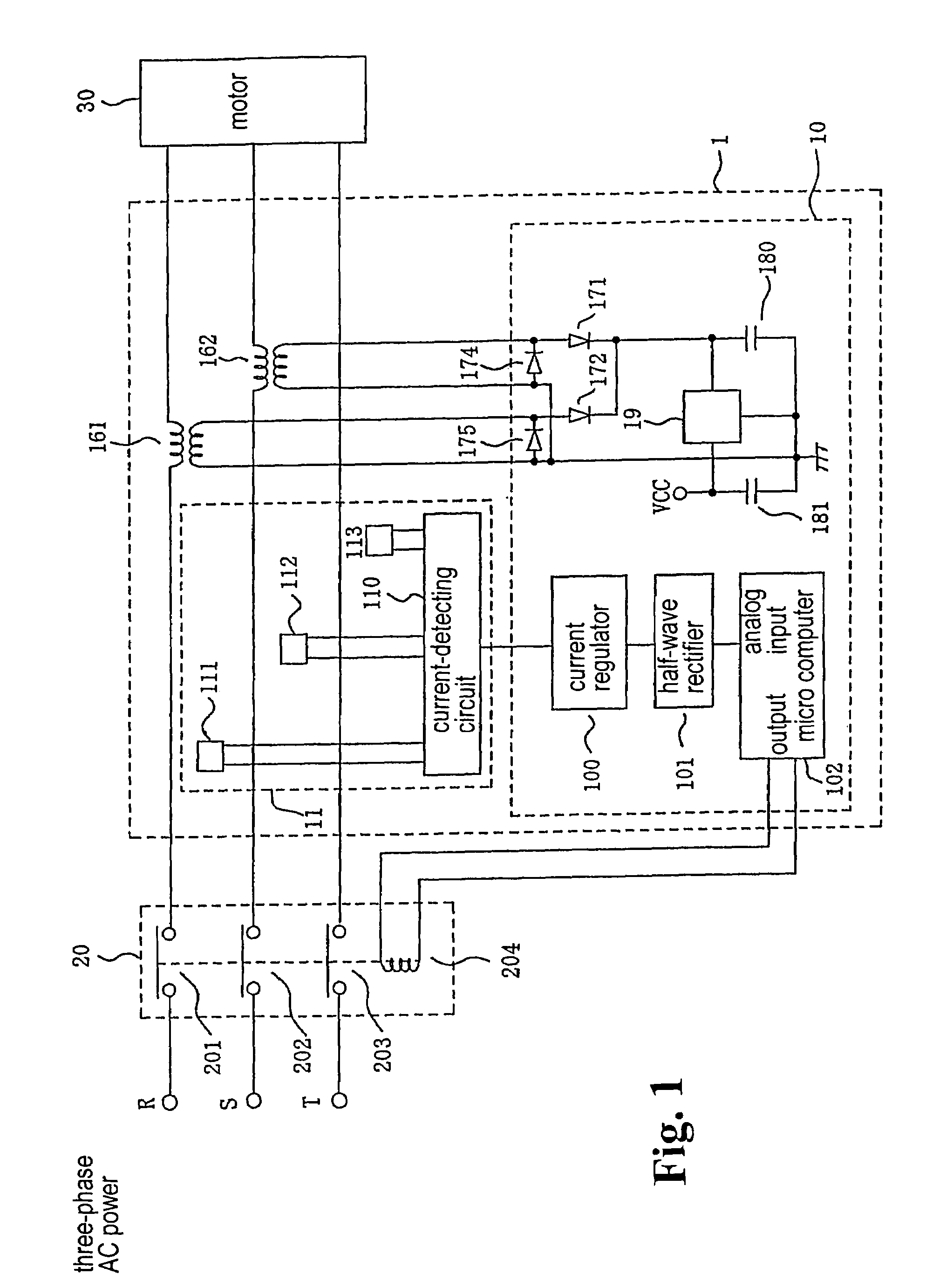
[0047]Hereunder, the present invention will be described. FIG. 1 is a schematic block diagram of an over-current protection device according to the present invention.

[0048]In FIG. 1, power-supply lines R, S, and T connected to a three-phase AC power-supply source (not shown) are linked with a motor 30 via a three-phase contactor 20 and a pair of power-supply transformers 161 and 162. A current detection unit 11 detects a current supplied via the power-supply lines R, S, and T for each phase. Even when one of the three phases incurs disconnection, it is required that the entire system be operated normally. Accordingly, the embodiment includes a pair of power-supply transformers 161 and 162. However, the transformer may be disposed for each phase. The contactor 20 has three contacts 201, 202, and 203, and each of the contacts is directly connected to the motor 30, or individually connected via primary coils of the power-supply transformers 161 and 162 through the power-supply lines R,...

second embodiment

[0060]FIG. 5 is a view showing a second embodiment with an improvement in the non-linear characteristic. As compared with that shown in FIG. 3a, the positive and negative bias magnetic fields are alternately applied to the MI elements 1a, 1b, and 1c, so that a difference in detected voltages upon the application of the individual bias magnetic fields is obtained, thereby improving the output linearity.

[0061]Reference numeral 12 designates frequency-dividing means for dividing a frequency of the signal output from the oscillating means 3. The dividing means 12 outputs a signal containing a frequency lower than that of the AC current fed to the MI elements 1a, 1b, and 1c. Reference numeral 13b designates second current-applying means for alternately applying positive and negative bias magnetic fields in response to the positive and negative output timings delivered from the frequency-dividing means 12. The second current-applying means 13b applies the output signal of the oscillating ...


PUM


Abstract

A current sensor which constitutes an overload protection apparatus and senses a current supplied from a power source to a load is constituted by providing a magnetic sensor having the effect of magnetic impedance (MI), an AC supply means which impresses AC on this sensor, a bias current supply means which supplies a bias current to a bias coil, a peak sensing means which senses the peak or a change in impedance of the magnetic sensor as a change in voltage, and a switch which selects the output of the peak sensing means in accordance with each phase. A holding means which holds switch outputs one after another and an amplification means are provided in common to enable current sensing for each phase. Thus, a range of current sensing is enlarged to reduce power consumption and cost.

Description

TECHNICAL FIELD OF THE INVENTION[0001]The present invention relates to an over-current protection device for detecting a current flowing through a conductor and for shutting oft the current when the current exceeds a predetermined threshold value. More particularly, the present invention relates to an over-current protection device capable of controlling power supplied to a load such as an electric motor.DESCRIPTION OF TECHNICAL BACKGROUND[0002]An over-current protection device detects a current flowing through a load such as a three-phase motor via a contactor, and shuts off the current flowing to the motor when the current exceeds a safe threshold value. Conventionally, such a device is provided with a bi-metal switching element, and a part or all of the current to the motor flows through the bi-metal switching element. That is, the current flows though a switch consisting of the bi-metal element so that the bi-metal element is heated according to an intensity of the current. When...

Claims


Application Information

Patent Timeline
Patent Type & Authority Patents(United States)
IPC IPC(8): H02H3/08H02H9/02G01R15/20H02H1/00H02H1/06
CPCG01R15/205H02H3/08H02H1/06H02H1/0007
Inventor KUDO, TAKAHIROTANAKA, JUNZOISHIKAWA, KIMITADA
Owner FUJI ELECTRIC FA COMPONENTS & SYST CO LTD
Why Eureka
Try Eureka