
Air conditioner

a technology for air conditioners and air filters, applied in the field of air conditioners, can solve the problems of noise transmission, increased overall weight of air conditioners, and increased air leakage between indoor parts and outdoor parts, and achieve the effect of simplifying the base fabrication process

Inactive Publication Date: 2006-04-25
LG ELECTRONICS INC
View PDF4 Cites 37 Cited by
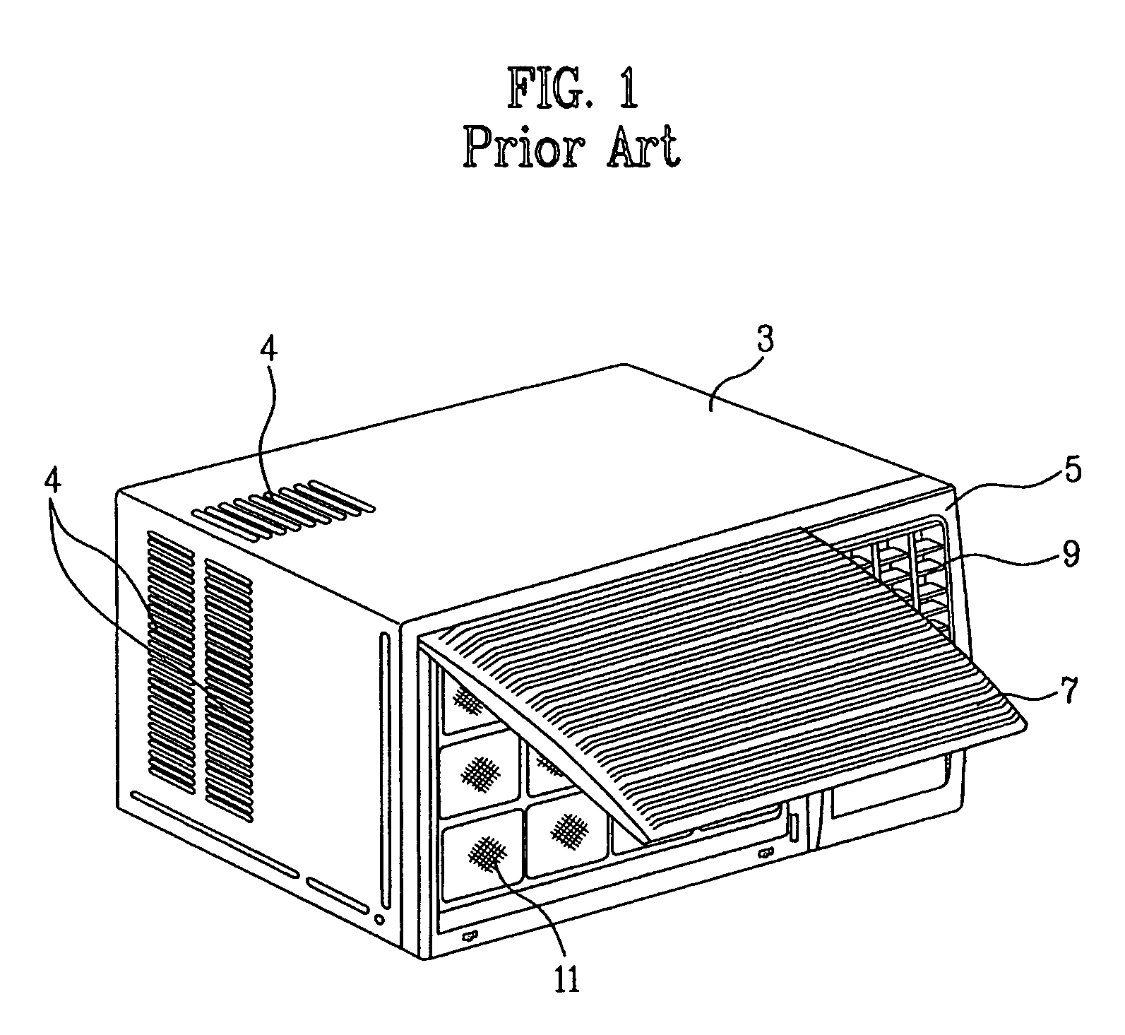
  • Summary
  • Abstract
  • Description
  • Claims
  • Application Information

AI Technical Summary

Benefits of technology

The present invention provides an air conditioner that solves problems of existing air conditioners by being lightweight, having fewer assembly parts, and ensuring a sealing between the indoor and outdoor parts. The air conditioner includes a base with parts constituting the indoor and outdoor parts installed thereon, a barrier integrated with the base for partitioning the upper space of the base into the indoor and outdoor parts, and a compressor loading part for loading a compressor at one side of the outdoor side base. The air conditioner is designed to simplify the base fabricating process and improve the performance of the air conditioner.

Problems solved by technology

However, the conventional air conditioner has the following drawbacks.
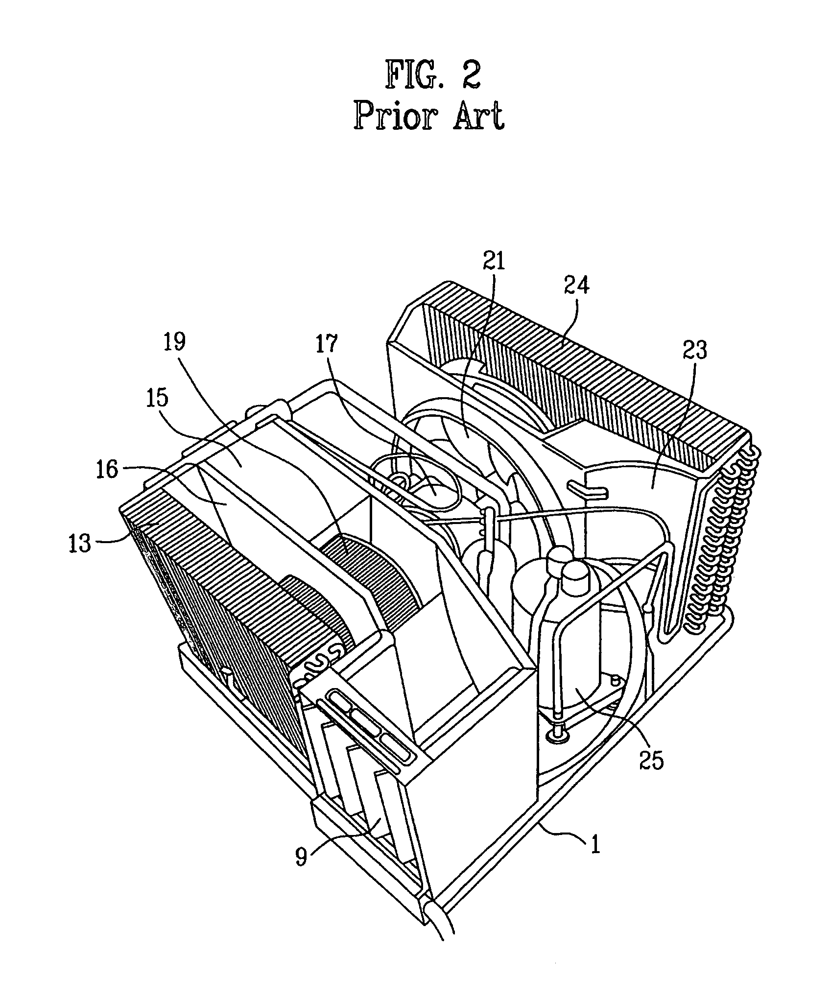
Since the base 1 is formed of a metallic plate, there is caused a drawback in that the overall weight of the air conditioner is increased.
Further, since the air guide 15 installed on the base 1, for partitioning the base 1 into the indoor part and the outdoor part is installed separately from the base 1, there may be caused a drawback in that air leakage between the indoor part and the outdoor part is generated through a gap between the base 1 and the air guide 15 or outdoor noise is transmitted to the indoor space.
Then, the fixing state of the fixing element may be damaged due to a vibration generated from the compressor, etc. while the compressor is driven.
In other words, a welded portion for fixing the fixing element to the base can be damaged due to repetitive vibration.
In this case, the noise resulting from the compressor vibration is much increased, and a connection part between the compressor and the refrigerant tube is damaged.
Additionally, once the fixing element is equipped in a completed base pan through a separate process, an assembly process is added so that fabrication costs are increased.

Method used


Image

  • Air conditioner
  • Air conditioner
  • Air conditioner

Examples


Embodiment Construction

[0062]Reference will now be made in detail to the preferred embodiments of the present invention, examples of which are illustrated in the accompanying drawings. Wherever possible, the same reference numbers will be used throughout the drawings to refer to the same or like parts.

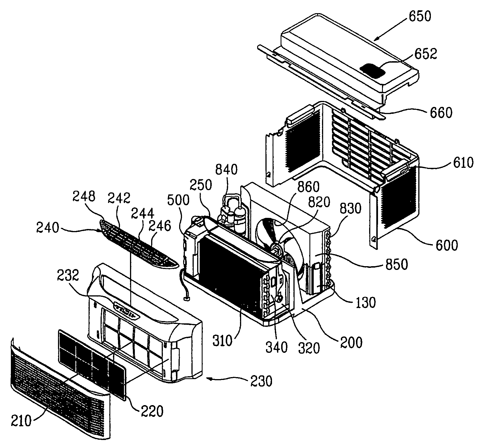
[0063]FIG. 3 is a perspective view illustrating an outer construction of an air conditioner in accordance with the present invention, and FIG. 4 is an exploded perspective view illustrating an air conditioner in accordance with the present invention.

[0064]Referring to FIGS. 3 and 4, the air conditioner is configured to include an indoor part, an outdoor part, and a base 110 integrated with a barrier 120.

[0065]Hereinafter, an element including the barrier 120 and the base 110 is called a base plate 100. The base 110 includes an indoor side base 110′ disposed at a lower portion of the indoor part of the air conditioner and an outdoor side base 110″ disposed at a lower portion of the outdoor part.

[0066]The indo...


PUM


Abstract

Disclosed is air conditioner having an indoor part and an outdoor part as one unit. The air conditioner including: an indoor part for inhaling an indoor air to exchange heat with the inhaled air through an indoor heat exchanger, and again discharging the heat-exchanged air into an indoor space; an outdoor part for inhaling an outdoor air to exchange heat with the inhaled air through an outdoor heat exchanger, and again discharging the heat-exchanged air into an outdoor space; a base having parts constituting the indoor part and the outdoor part installed thereon; and a barrier integrated with the base, for partitioning an upper space of the base into the indoor part and the outdoor part.

Description

[0001]This application claims the benefit of the Korean Application Nos. P2003-0004950 and P2003-0004953 both filed on Jan. 24, 2003 and P2003-0005365 filed on Jan. 27, 2003, which are hereby incorporated by reference.BACKGROUND OF THE INVENTION[0002]1. Field of the Invention[0003]The present invention relates to an air conditioner, and more particularly, to an air conditioner provided with an indoor part and an outdoor part integrated as one unit.[0004]2. Discussion of the Related Art[0005]Generally, air conditioner is installed at a window or the like of a building to air-condition an inner space of the building.[0006]FIG. 1 is a perspective view illustrating appearance of a conventional air conditioner, and FIG. 2 is a perspective view illustrating an inner construction of a conventional air conditioner.[0007]As shown in FIGS. 1 and 2, the conventional air conditioner includes a bottom base 1 of metal. Both sides and upper surface of the air conditioner are covered with a cabinet...

Claims


Application Information

Patent Timeline
Patent Type & Authority Patents(United States)
IPC IPC(8): F25D23/12F24F1/02F24F13/20
CPCF24F1/027F24F1/12F24F13/20F24F2013/205F24F13/24F24F2013/202
Inventor KIM, GYU RAKHA, JONG MINCHANG, WOO SUNG
Owner LG ELECTRONICS INC
Learn More