Flexible pipe with high axial compression strength and method for making same

a flexible pipe and axial compression technology, applied in the direction of flexible pipes, pipes, mechanical devices, etc., can solve the problems of reducing the tensile strength of the flexible pipe, the tendency to axial shorten the pipe, and the end of the flexible pipe being lowered into the sea, so as to ensure the flexibility of the pipe, limit contact fatigue, and ensure the mechanical characteristics of the flexible pipe. tensile strength is not modified

Inactive Publication Date: 2006-04-25
INST FR DU PETROLE +1
View PDF11 Cites 21 Cited by
  • Summary
  • Abstract
  • Description
  • Claims
  • Application Information

AI Technical Summary

Benefits of technology

[0015]The present invention aims to limit the play between the reinforcing wires of a tensile armouring layer so as to reduce transverse motions while keeping the pipe flexibility. The wires can freely move in the direction of the greatest dimension of the wires. In order to control the play between two wires of an armouring layer, on the one hand, the invention aims to limit the global play, i.e. the value of the sum of the plays between wires measured on the circumference of an armouring layer and, on the other hand, the invention aims to limit the maximum value of the play between two contiguous wires.
[0028]The major advantage of the layout of the wires according to the invention is to eliminate the possibilities of transverse displacement of the wires while providing the pipe with the required flexibility and mechanical characteristics. On the one hand, the reinforcing wires can freely move longitudinally in relation to one another to ensure flexibility of the pipe and, on the other hand, the mechanical characteristics of the pipe as regards tensile stresses are not modified.
[0029]Furthermore, when the reinforcing wires are in contact with plastic elements, these elements limit contact fatigue and thus prevent wear of the wires.

Problems solved by technology

However, in deep-sea structures, closing the end of the pipe lowered into the sea has drawbacks.
In fact, the flexible pipe is subjected to high axial compression stresses due to the outside hydrostatic pressure, which are applied onto the end of the pipe.
The compression stresses applied on the end of the pipe cause a tendency to axial shortening of the pipe.
However, this solution is limited by the maximum allowable size of the wires, it imposes higher stresses in the tensile armourings.

Method used


Image

  • Flexible pipe with high axial compression strength and method for making same
  • Flexible pipe with high axial compression strength and method for making same
  • Flexible pipe with high axial compression strength and method for making same

Examples


first embodiment

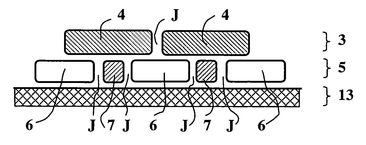
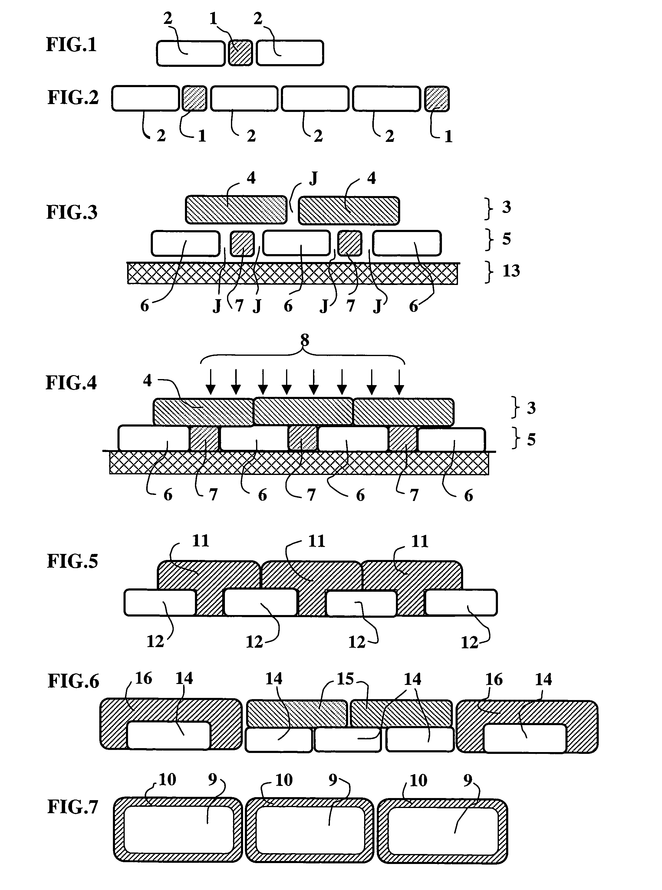
[0039]According to the invention illustrated by FIG. 1, a tensile armouring layer is made by depositing an intermediate wire (1) between two reinforcing wires (2). The laying frequency of an intermediate wire between two reinforcing wires notably depends on the size of the pipe and of the wires, and on the performances of the tensile armouring layer manufacturing means. As shown in FIG. 2, intermediate wires (1) can be evenly deposited after three consecutive reinforcing wires (2). The intermediate wires can also be unevenly distributed on the circumference of the layer. Laying of reinforcing wires (2) and of intermediate wires (1) of the tensile armouring layers on the flexible pipe is carried out according to the manufacturing principle known from the prior art.

[0040]The section of a wire designates a view along a section orthogonal to the direction of the wire length. The thickness of the wire designates a dimension of the wire section, the thickness extending in a radial directi...

second embodiment

[0055]FIG. 7 shows the invention. Reinforcing wires (9) forming the tensile armouring layer are coated with a sheath (10) made of a more supple material than the material used for the reinforcing wires. A sheath (10) can be applied onto a reinforcing wire (9). Without departing from the scope of the invention, the reinforcing wires can be coated with a more supple material than the material used for the reinforcing wires on certain faces only. For example, only the faces in contact with the elements of a tensile armouring layer are coated with such a material. Any method known to the man skilled in the art can be used for coating the reinforcing wires, notably extrusion, splash, sticking.

[0056]The tensile armouring layer of FIG. 7 is made using also the helical laying principle used for reinforcing wires (9) but, before the laying operation, sheath (10) is applied. The reinforcing wires provided with a sheath are laid on the flexible pipe in such a way that the play between two succ...

third embodiment

[0061]According to the invention, each wire forming a tensile armouring layer is clamped to the neighbouring wires of the same armouring layer. For example, the section of the wires can be T-shaped or U-shaped. This clamping allows to control the interstice between two contiguous armouring wires. It is also possible to limit displacement of the wires. When the flexible pipe is in service, each wire is held in place at the point where the buckling stress is maximum by an adjacent wire having a lower buckling stress.


PUM


Abstract

The present invention relates to a flexible pipe structure wherein transverse displacement caused by buckling of the elongate elements of a tensile armouring layer when the pipe is being laid or used in deep sea is limited. The invention aims to reduce the play between the elongate elements of the tensile armouring layer so as to limit transverse displacement possibilities while providing the pipe with the required flexibility and mechanical characteristics. The elongate elements can freely move longitudinally in relation to one another to ensure flexibility of the pipe.

Description

FIELD OF THE INVENTION[0001]The present invention relates to a flexible pipe structure and to a method for making same. The object of the invention is to limit buckling of the elongate elements used as mechanical reinforcement armouring for the structure of a flexible pipe.[0002]Flexible pipes are notably used in the petroleum industry for carrying petroleum from a wellhead located at the sea bottom to process facilities located at the surface. The pipes laid on the sea bottom, commonly referred to as flowlines, mainly undergo static mechanical stresses, whereas the pipes connecting the sea bottom to the surface, commonly referred to as risers, undergo static and dynamic mechanical stresses.[0003]The term wire used in the present description refers to elongate elements one dimension of which is very large in relation to the others.FIELD OF THE INVENTION[0004]The structure of a flexible pipe, notably described in standards API 17 B and API 17 J established by the American Petroleum I...

Claims


Application Information

Patent Timeline
Patent Type & Authority Patents(United States)
IPC IPC(8): F16L11/00F16L11/08
CPCF16L11/081
Inventor AVERBUCH, DANIELLEROY, JEAN-MARCCOUTAREL, ALAIN
Owner INST FR DU PETROLE
Why Eureka
Try Eureka