Percussion device

a percussion device and percussion technology, applied can solve problems such as harmful vibrations in the field of percussion devices

Inactive Publication Date: 2006-04-25
MK PRODR MEKANIK & KEMI
View PDF19 Cites 10 Cited by
  • Summary
  • Abstract
  • Description
  • Claims
  • Application Information

AI Technical Summary

Benefits of technology

[0005]The present invention aims at obviating the above-mentioned disadvantage of the percussion device known by U.S. Pat. No. 2,094,185 and at providing an improved percussion device. Thus, a primary object of the invention is to provide a percussion device in which the motions of the drive spindle via the bearings thereof cannot be transferred to the housing and cause vibrations therein. Furthermore, the percussion device should be structurally simple and be driven by an arbitrary driving source, in particular an electric motor, which may operate wherever electric power is available.

Problems solved by technology

This implies that tangential forces of the drive spindle are transferred to the housing and cause harmful vibrations therein.

Method used


Image

  • Percussion device
  • Percussion device

Examples


Embodiment Construction

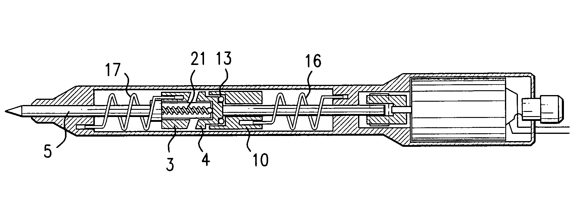
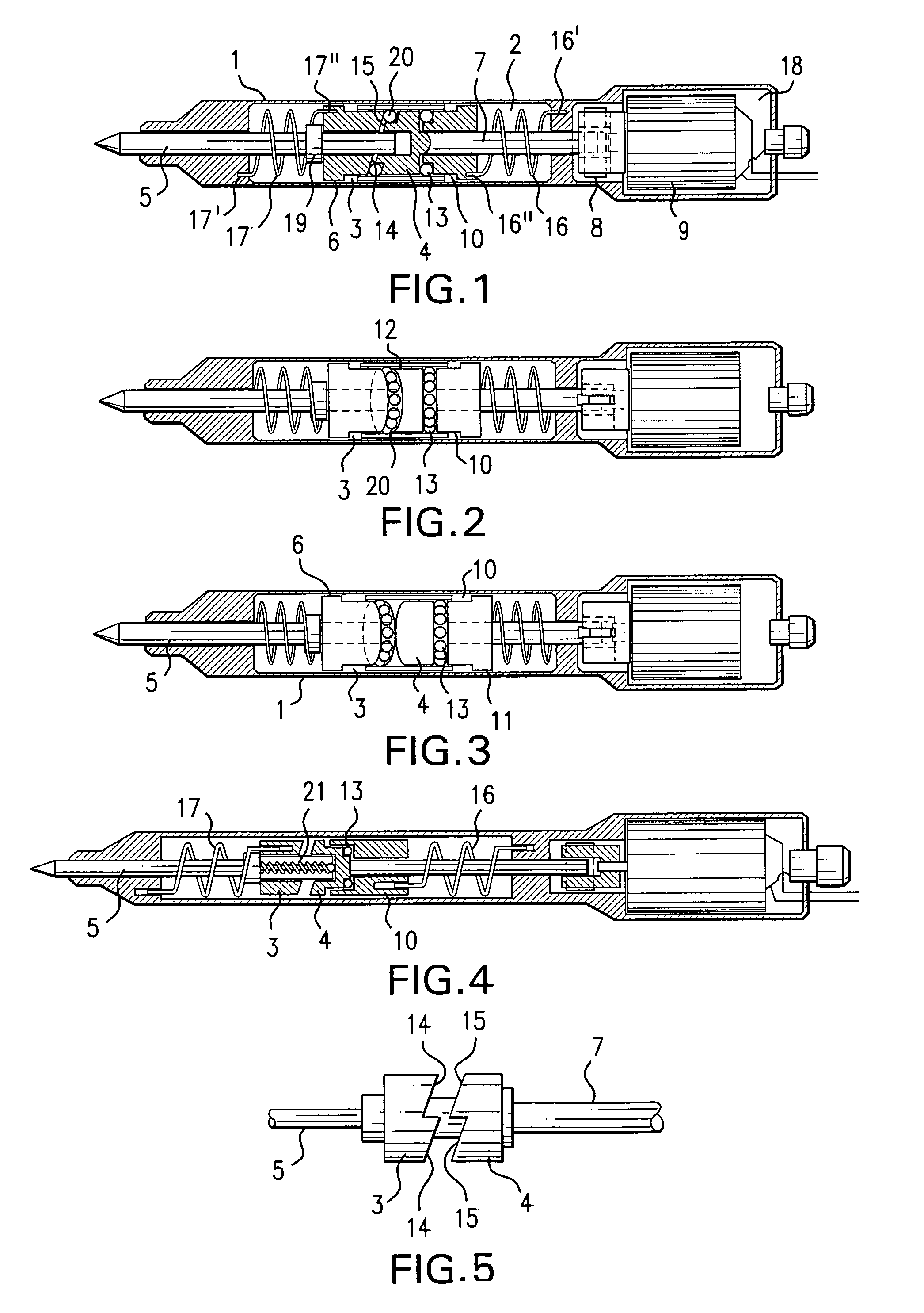
[0012]The percussion device shown in FIGS. 1–3 comprises a housing in its entirety denominated 1 and which in the example is of a long narrow, cylindrical primary basic shape. A cavity or chamber 2 in which an impact body 3 is disposed is delimited inside the housing, which impact body interacts with a balancing body 4. An impact pin 5 is connected to a front end of the impact body 3, which pin protrudes a distance from the front end of the housing 1. Advantageously, the impact body 3 is of a cylindrical basic shape and is formed with a front flange 6, the outer diameter of which is slightly smaller than the inner diameter of the chamber 2.

[0013]From the rear end of the balancing body 4, a rotatable drive spindle 7 extends, which via a coupling 8 (or gear) is connected to a driving source 9. According to the preferred embodiment of the invention, said driving source consists of an electric motor, which may be mains-operated or battery-powered. The drive spindle 7 is rotatably journa...


PUM

PropertyMeasurementUnit
rotationaaaaaaaaaa
strengthaaaaaaaaaa
tangential forcesaaaaaaaaaa

Abstract

Percussion device, includes a housing and two movable bodies, an impact body for an impact pin protruding from the housing, and a balancing body for counterbalancing impact motions of the impact body. The housing includes springs, which constantly strive to bring the bodies towards each other and against the action of which the bodies may be separated axially. The balancing body is rotatable, via a drive spindle connected to a driving source the spindle being mounted in a bearing member, at least one of the bodies including an oblique surface, which, by contact against the other body, transforms the rotary motion of the balancing body into axial motions of the impact body. Rotation of the bearing member is prevented by a helical pressure spring attached to the bearing member and the housing. In this way, tangential vibrations cannot be transferred from the drive spindle to the housing.

Description

[0001]This application is a 371 of PCT / SE02 / 01710 filed Sep. 23, 2002.TECHNICAL FIELD OF THE INVENTION[0002]This invention relates to a percussion device comprising a housing and, inside the same, two bodies being movable to and fro each other along a common geometric axis, viz. a first body or impact body for an impact pin protruding from the housing, and a second body or balancing body having the purpose of counterbalancing the impact motions of the impact body so as to anti-vibrate the device in its entirety, and springs which always strive to bring the bodies towards each other and against the action of which said bodies may be separated axially, the balancing body, but not the impact body, being rotatable, and at least one of the bodies including a surface that is oblique in relation to said geometrical axis and, by contact with at least one oblique surface, cog or stud of the other body, arranged to transform the rotary motion of the balancing-body into axial motions of the im...

Claims


Application Information

Patent Timeline
Patent Type & Authority Patents(United States)
IPC IPC(8): B25D11/00B25D11/10B44B3/00
CPCB44B3/005B25D11/102
Inventor RASK, THOMAS
Owner MK PRODR MEKANIK & KEMI
Why Eureka
Try Eureka