Rear suspension for wheelchair

Inactive Publication Date: 2006-04-25
CHELGREN ERIC MARK
View PDF9 Cites 22 Cited by
  • Summary
  • Abstract
  • Description
  • Claims
  • Application Information

AI Technical Summary

Benefits of technology

[0007]The fork includes a large axle housing to receive the axle of the large wheel. The fork has two separated tines which are joined at their lower edges by a transverse wall which carries a recess which receives the lower end of the polymer cylinder. Each tine terminates with a ring which, with the ring of the other tine, forms the large axle housing. Each ring contains a small gap in its circumference and the distal parts of the lower edges of the rings are joined by a web. The web may be drawn toward the transverse wall of the fork by a screw which can be adjusted, making the large axle housing adjustable in circumference so that the axle of the large rear wheel can be held securely within the axle housing of the fork.
[0008]The bottom of the clamp base inc

Problems solved by technology

Rotation of the fork relative to the hinge is limited by surfaces on the fork and on the base near the hinge such that the fork cannot rotate away from the clamp base to the extent that the polymer

Method used


Image

  • Rear suspension for wheelchair
  • Rear suspension for wheelchair
  • Rear suspension for wheelchair

Examples


Embodiment Construction

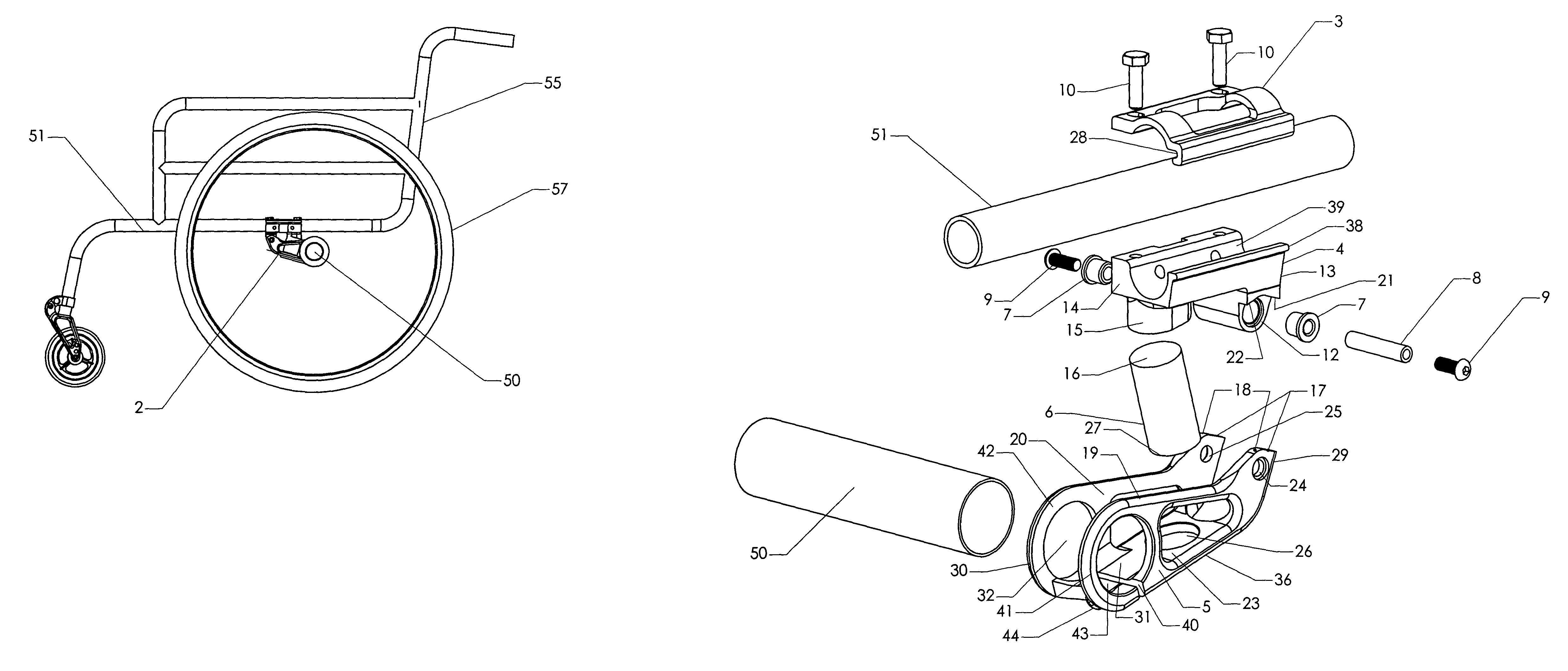
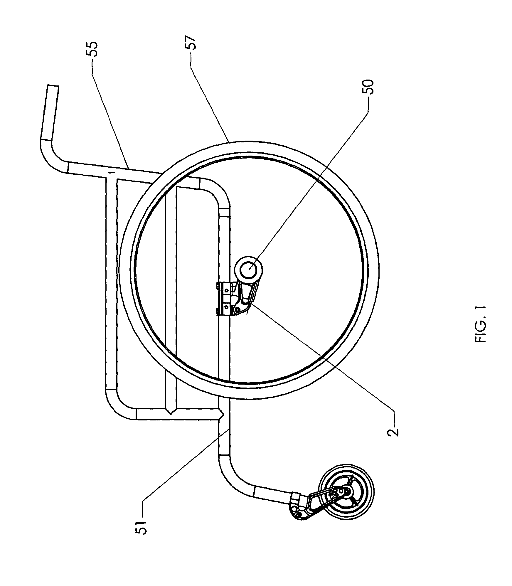
[0019]FIG. 1 discloses a wheelchair 55 equipped at each rear wheel 57 thereof with a rear suspension element 2 according to the present invention. A horizontal frame member 51 on each side of the wheelchair 55 has one of rear suspension elements 2 clamped thereto. Each rear wheel 57 is mounted at its axle 50 to a rear suspension element 2.

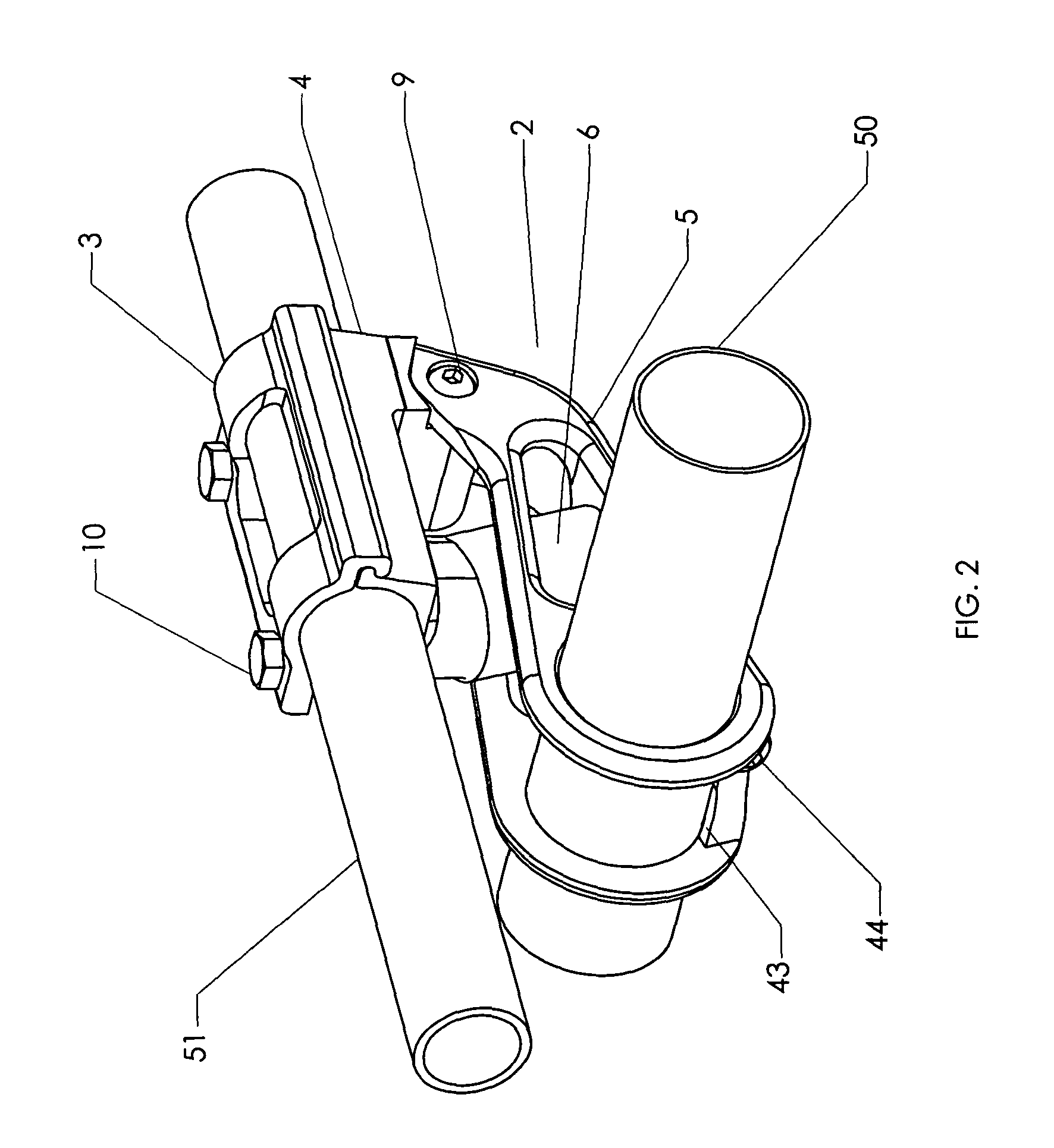
[0020]FIG. 2 shows a perspective of the invention rear suspension element 2 suspending rear wheel axle 50 (with the rear wheel removed) of a manual wheelchair. The invention is shown mounted to a horizontal frame member 51 (cut away) of the manual wheelchair.

[0021]Referring now to FIGS. 2–5, the invention comprises a clamp base 4 which may be secured to horizontal frame member 51 of the wheelchair by use of enclosing member 3 which may be securely fastened to clamp base 4 by use of bolts 10. Enclosing member 3 includes longitudinal notch 28 into which elongate ridge 38 of clamp base 4 is received before bolts 10 are installed. Clamp base 4 and encl...


PUM


Abstract

A shock absorbing suspension for the large rear wheels of a wheelchair is disclosed. A fork element is hinged at one end to a clamping member which attaches to a horizontal frame member of the wheelchair. A cylindrical solid polymer shock absorber cushions the movement of the fork element toward the clamping member. The free end of the fork element includes an axleway for the axle of a large wheelchair wheel. The movement of the fork element relative to the clamping member is limited by abutting surfaces on the fork element and the clamping member.

Description

CROSS-REFERENCE TO RELATED APPLICATIONS[0001]This application claims priority from copending provisional patent application entitled “Rear Suspension for Wheelchair”, Ser. No. 60 / 412,073 filed Sep. 19, 2002. The disclosure of provisional patent application Ser. No. 60 / 412,073 is hereby incorporated in its entirety.STATEMENT REGARDING FEDERALLY SPONSORED RESEARCH OR DEVELOPMENT[0002]Not Applicable.BACKGROUND OF THE INVENTION[0003]The present invention pertains to wheelchairs and particularly to suspension of the large rear wheels of wheelchairs which are manually operable as well as those that are powered by self-contained motors.[0004]In the typical manual wheelchair each rear wheel is a large wheel mounted to the frame of the wheelchair without any provision for absorption of shocks or damping of vibration of the wheelchair. In such a wheelchair, shocks and vibrations arising from irregularities and defects in the traveled surface are transmitted through the rear wheels to the whee...

Claims


Application Information

Patent Timeline
IPC IPC(8): A61G5/10
CPCA61G5/10A61G2005/1054A61G2005/1078Y10S297/04B60G2202/143B60G2204/143B60G2300/24B60G2200/31A61G5/1054A61G5/1078
Inventor CHELGREN, ERIC MARK
Owner CHELGREN ERIC MARK
Why Eureka
Try Eureka