Multi-band antenna

a multi-band antenna and antenna technology, applied in the direction of resonant antennas, separate antenna unit combinations, radiating element structural forms, etc., can solve the problem that the antenna configuration is not steady enough to stand the resistance test, and achieve good impedance matching

Inactive Publication Date: 2006-04-25
HON HAI PRECISION IND CO LTD
View PDF9 Cites 52 Cited by
  • Summary
  • Abstract
  • Description
  • Claims
  • Application Information

AI Technical Summary

Benefits of technology

[0011]The present invention do not only economize the limit space of notebook computer, but also have good impedance matching. The whole multi-band antenna is made of sheet metal so that it can pass the panel vibrational test of an electronic device easily.

Problems solved by technology

Further more, because the conventional antenna is manufactured as printed circuit, the configuration of the antenna is not steady enough to stand the resistance test.

Method used


Image

  • Multi-band antenna
  • Multi-band antenna
  • Multi-band antenna

Examples


Embodiment Construction

[0022]Reference will now be made in detail to a preferred embodiment of the present invention.

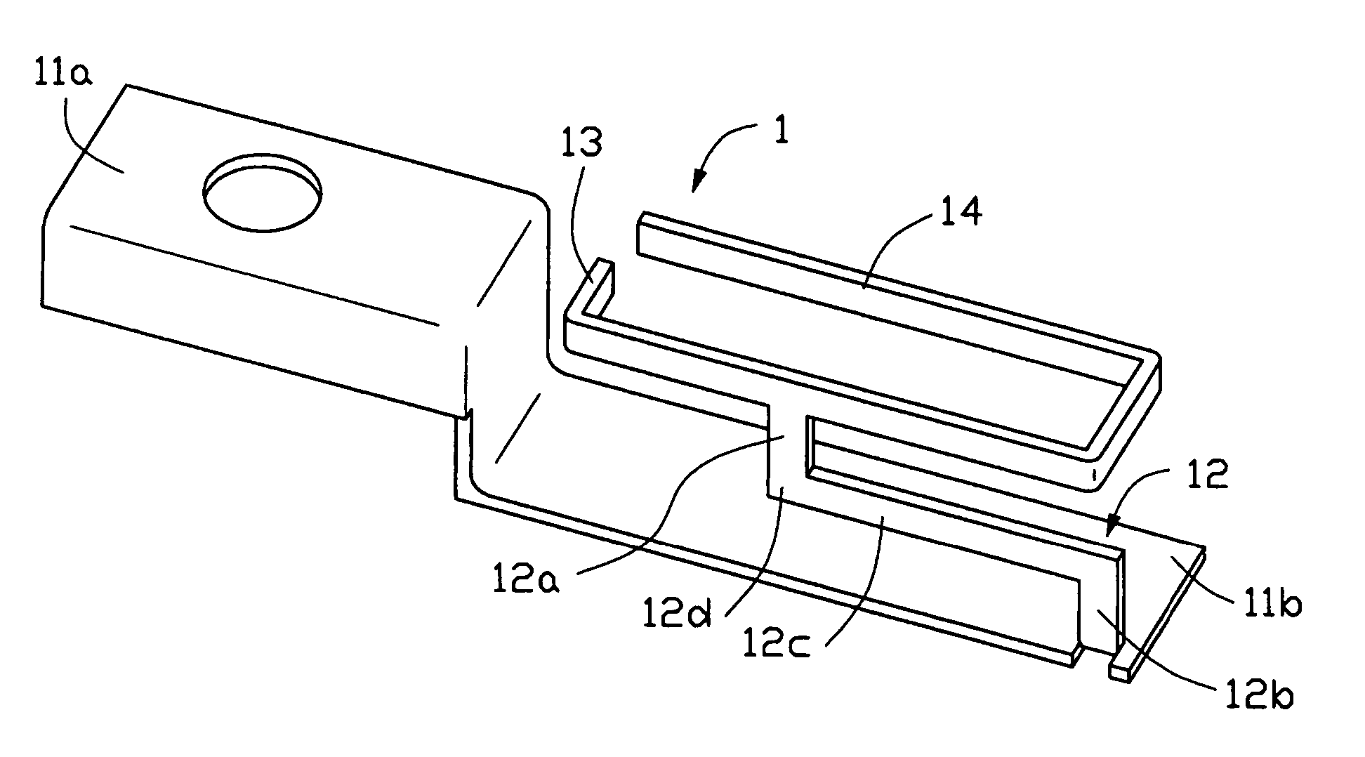
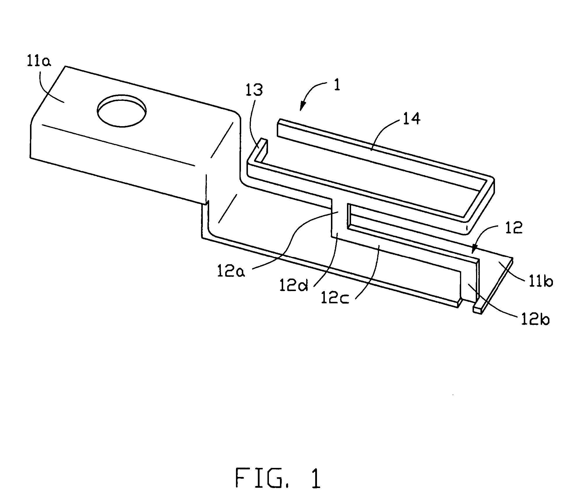
[0023]Referring to FIG. 1, a multi-band inverted-F antenna 1 according to the present invention is made of sheet metal and comprises a Z-shaped ground portion (not labeled), a step-shaped connecting portion 12, a first radiating arm 13 and a second radiating arm 14.

[0024]The Z-shaped ground portion comprises a fixing section 11a located on the left-hand side (as viewed from FIG. 1), a ground section 11b located on the right-hand side and a vertical conducting plate (not labeled) connecting the fixing section 11a and the ground section 11b. The fixing section 11a comprises a horizontal plane (not labeled) which is parallel to the ground section 11b and defines a circular screw hole (not labeled), and a vertical plane (not labeled) extending downwardly from the horizontal plane and perpendicular to the ground section 11b. The horizontal plane and the vertical plane are provided for cooperativ...


PUM


Abstract

A multi-band antenna (1) used for an electronic device includes a Z-shaped ground portion, a first L-shaped radiating arm (13) positioned above a ground section of the ground portion, a second U-shaped radiating arm (14) extending from the first radiating arm, a connecting portion (12) connecting the two radiating arms with the ground portion. The first and the second radiating arms are coplanar with each other. The ground portion, the connecting portion, the radiating arms and the feeder cable form two inverted-F antennas operating in different frequency bands.

Description

BACKGROUND OF THE INVENTION[0001]1. Field of the Invention[0002]The present invention relates generally to an antenna, and more particularly to a multi-band inverted-F antenna which can be used with an electronic device and allows the electronic device to communicate within different frequency bands.[0003]2. Description of the Prior Art[0004]With the development of wireless local area networks (WLANs) and wireless personal area networks (WPANs) in the recent years, many protocols or standards are developed to adapt to the newest wireless networks accompanyingly. 802.11b, 802.11g, HomeRF, Zigbee which appears in 2003 and is developing rapidly now, Bluetooth1.0, and Bluetooth 2.0 which is under research now all require a working frequency in 2.4 GHz band. Meanwhile, 802.11a which is put forward in 2000 and 802.11n which is still a plan now all require a working frequency in 5 GHz band.[0005]To match the wireless networks requirement and the standards mentioned above, many portable ter...

Claims


Application Information

Patent Timeline
Patent Type & Authority Patents(United States)
IPC IPC(8): H01Q1/38H01Q1/24H01Q9/04H01Q21/30
CPCH01Q1/242H01Q21/30H01Q9/0421
Inventor HUNG, ZHEN DATAI, LUNG-SHENGKE, YUN-LUNG
Owner HON HAI PRECISION IND CO LTD
Why Eureka
Try Eureka