Combined display-camera for an image processing system

a technology of image processing system and display screen, applied in the field of combined display and camera, can solve the problems of affecting the appearance of the image, affecting the affecting the image quality of the image, so as to achieve the effect of reducing the difficulty of camera configuration, and reducing the size of the system

Inactive Publication Date: 2006-04-25
UNILOC 2017 LLC
View PDF18 Cites 204 Cited by
  • Summary
  • Abstract
  • Description
  • Claims
  • Application Information

AI Technical Summary

Benefits of technology

[0010]Advantageously, the present invention solves the above-noted eye contact and “fish eye” distortion problems, and avoids the need for implementation of a camera adjacent to or behind a display. In addition, the combined display-camera of the present invention is suitable for use in a wide variety of image processing systems, including video-camera-based systems such as video conferencing systems, video surveillance and monitoring systems, and human-machine interfaces.

Problems solved by technology

A significant problem that can arise in the system 100 of FIG. 1 is that it is difficult to configure the camera 102 and display 104 such that it appears to both the on-site and remote users that they are making eye contact via the generated images.
However, in applications such as portable video conferencing units and human-machine interfaces, users often locate themselves very close to the display, such that the eye contact problem is accentuated.
Unfortunately, this approach requires placement of a video camera at a particular distance behind the display screen, which can substantially increase the size of the system.
In addition, such an approach is unable to avoid certain important types of image-related distortion, such as the so-called “fish eye” distortion which results in a single-camera system when a user is situated close to the display.

Method used


Image

  • Combined display-camera for an image processing system
  • Combined display-camera for an image processing system
  • Combined display-camera for an image processing system

Examples


Embodiment Construction

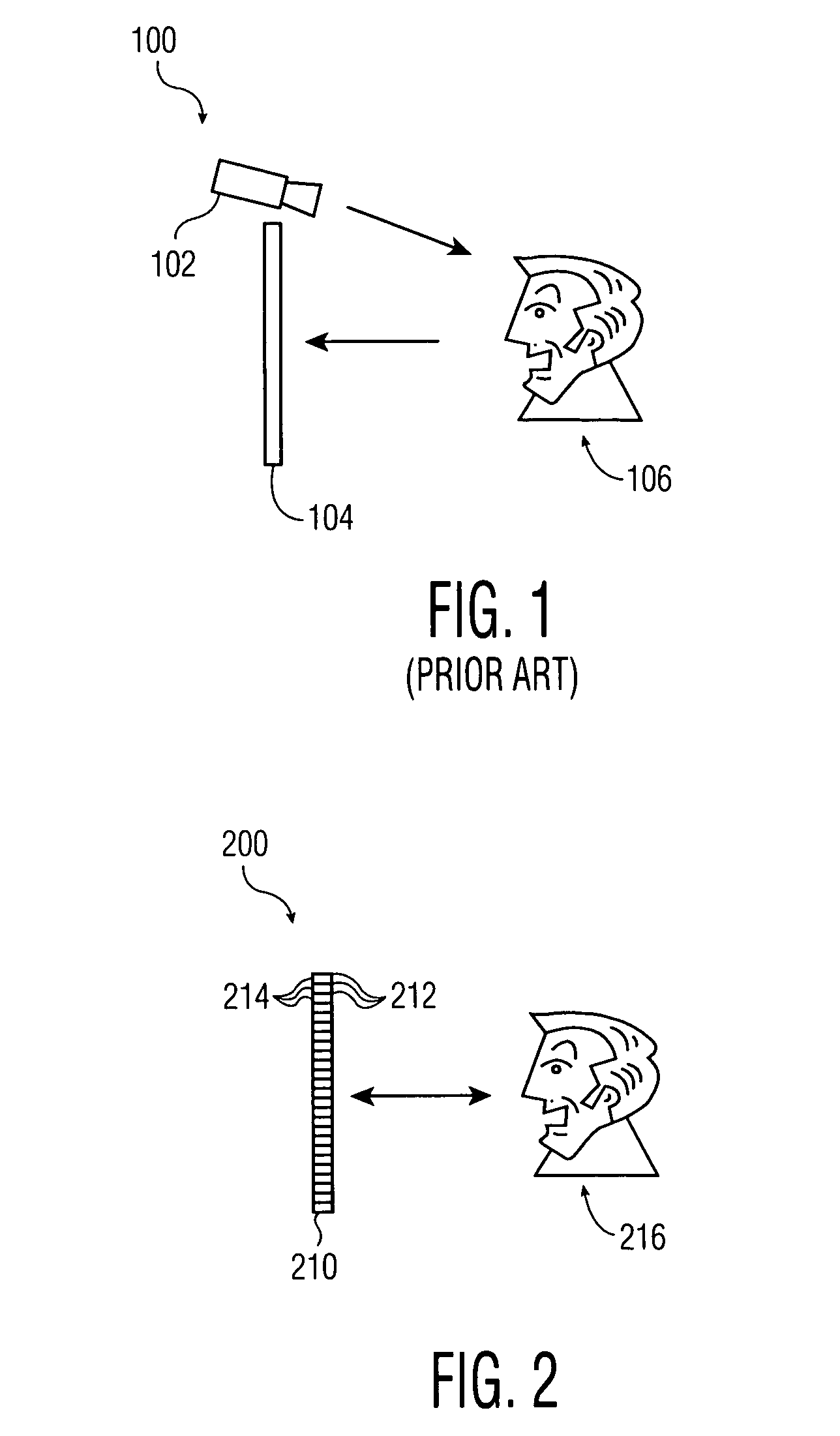
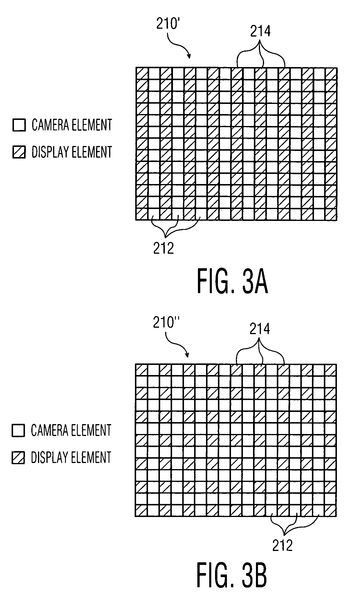
[0017]FIG. 2 shows a portion of an image processing system 200 in accordance with an illustrative embodiment of the present invention. The system 200 includes a combined display-camera 210 which is configured as an array of alternating display elements 212 and camera elements 214. Each of the display elements 212 may be a conventional display element such as a liquid crystal display (LCD) element, and may correspond to one or more image pixels. Each of the camera elements 214 may be a charge-coupled device (CCD), photosensor or other type of conventional image sensor, or a group of multiple such image sensors. In operation, the image sensing outputs of the set of camera elements 214 are combined using conventional image signal processing techniques so as to provide a desired composite image of a scene.

[0018]The camera elements 214 each preferably have a narrow field of view, and are interspersed with the display elements 212 substantially in a common plane so as to form a flat panel...


PUM


Abstract

An image processing system includes a combined display-camera having an array of interspersed display elements and camera elements, arranged substantially in a common plane of a flat panel or other display. Each of at least a subset of the camera elements has one or more imaging angles associated therewith, with the one or more imaging angles being selected to provide a desired imaging operation for the combined display-camera. The imaging angles of the camera elements can be selected to provide an imaging operation which approximates that of a lens-based single-camera system, a pin-hole camera system or other type of system. Each of the camera elements may include multiple image sensors, such that different imaging angles can be set for the different image sensors of a given camera element, and different perspectives of a scene can be generated in the image processing system.

Description

FIELD OF THE INVENTION[0001]The present invention relates generally to the field of image processing systems, and more particularly to a combined display and camera suitable for use in such systems.BACKGROUND OF THE INVENTION[0002]Many conventional image processing systems utilize a camera in conjunction with a video display. FIG. 1 shows an example of such an arrangement in the form of an image processing system 100 which includes a camera 102 and a separate display 104. The system 100 may be used in a video conferencing application or other suitable application in which the camera 102 generates an image of an on-site user 106 and the display 104 presents images of one or more remote users to the user 106.[0003]A significant problem that can arise in the system 100 of FIG. 1 is that it is difficult to configure the camera 102 and display 104 such that it appears to both the on-site and remote users that they are making eye contact via the generated images. This eye contact problem ...

Claims


Application Information

Patent Timeline
Patent Type & Authority Patents(United States)
IPC IPC(8): H04N5/232H04N5/222H04N5/225H04N5/335H04N5/66H04N7/14
CPCH04N7/144H04N3/155H04N25/76H04N7/14
Inventor COLMENAREZ, ANTONIO J.LEE, MI-SUENBRODSKY, TOMASSTRUBBE, HUGO J.JANSSEN, PETER J.PASHLEY, MICHAEL D.
Owner UNILOC 2017 LLC
Why Eureka
Try Eureka