Electronic apparatus with a housing for seeing inside

a technology for electronic equipment and housings, applied in the direction of electrical apparatus casings/cabinets/drawers, coupling device connections, instruments, etc., can solve the problems of unfavorable influence of electromagnetic radiation on users and the environment, electronic equipment may fail to properly function, and the inner structure of electronic equipment becomes more and more complicated, so as to achieve the effect of light weigh

Active Publication Date: 2006-04-25
MICRO-STAR INTERNATIONAL
View PDF23 Cites 29 Cited by
  • Summary
  • Abstract
  • Description
  • Claims
  • Application Information

AI Technical Summary

Benefits of technology

[0009]It is an advantage of the present invention that a user can see inside the electronic apparatus, and dust is kept from entering into the electronic apparatus.
[0010]It is another advantage of the present invention that, compared to conventional housings made of metal, the housing according to the present invention is lighter in weight.
[0011]These and other objectives of the present invention will no doubt become obvious to those of ordinary skill in the art after reading the following detailed description of the preferred embodiment that is illustrated in the various figures and drawings.

Problems solved by technology

Electromagnetic radiation has an unfavorable influence on users and the environment, i.e. electromagnetic radiation interference, so that most countries and regions have set up standards for electromagnetic radiation.
Additionally, as the speed of data processing in computers improved, the inner structure of the electronic apparatus becomes more and more complicated.
An electronic apparatus may fail to properly function simply due to defect or malfunction of only one part.
For instance, if a heat radiating fan or a water-cooling system breaks down so that the electronic apparatus cannot operate, it is difficult to discover because the conventional electronic apparatus is covered with a metal housing.
However, the plurality of holes has no corresponding protection so that it is unable to keep dust from entering into the housing.
Moreover, the light entering into the housing via the holes is horizontal to a motherboard, so that it is not easy to see inside the housing.

Method used


Image

  • Electronic apparatus with a housing for seeing inside
  • Electronic apparatus with a housing for seeing inside
  • Electronic apparatus with a housing for seeing inside

Examples


first embodiment

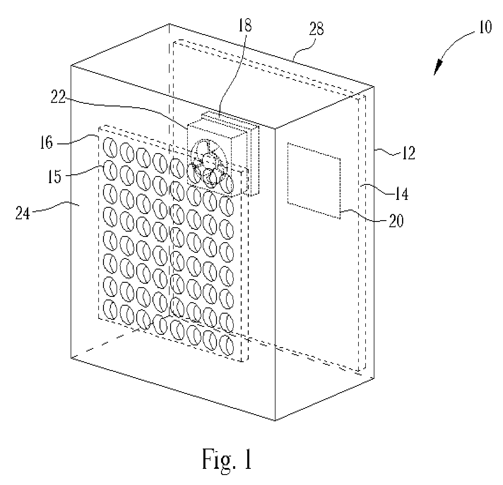
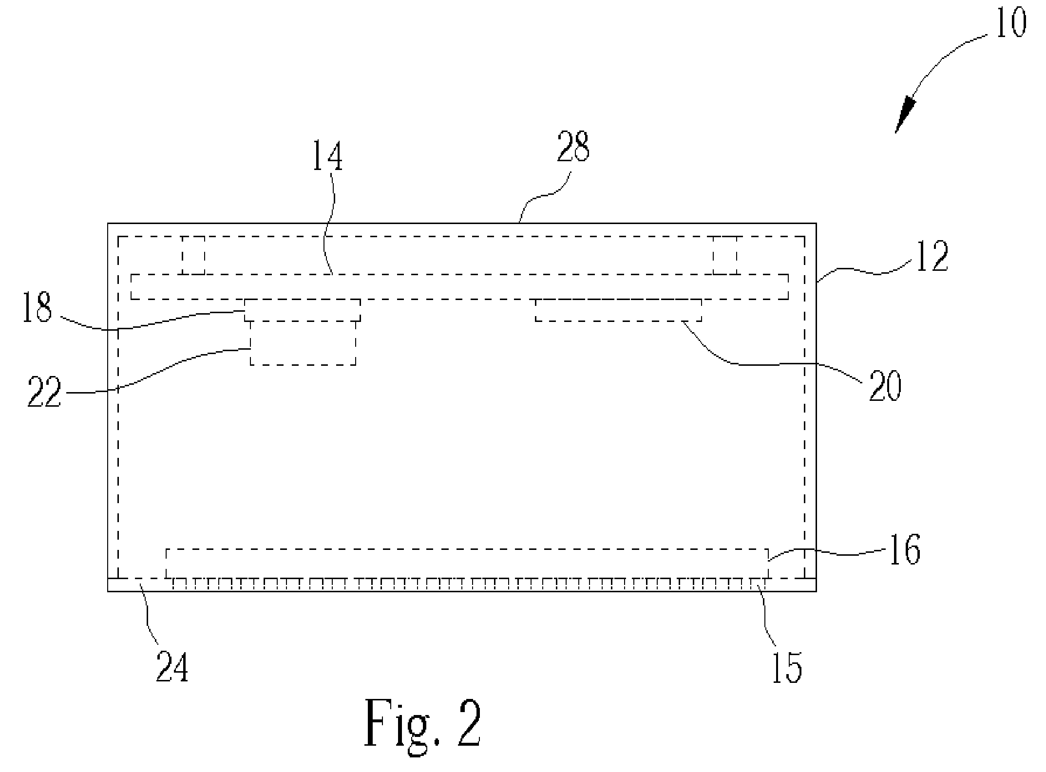
[0019]Please refer to FIG. 1 showing a perspective view of an electronic apparatus 10 according to the present invention, and FIG. 2 showing a perspective top view of the electronic apparatus 10. The electronic apparatus 10 includes a housing 12, the housing 12 has a plurality of holes 15 on a first side wall 24. A motherboard 14 and a transparent dust-proof member 16 are installed in the electronic apparatus 10. The motherboard 14 is installed on a second side wall 28, and the transparent dust-proof member 16 is installed parallel to the first side wall having the plurality of holes 15. A processor 18 for processing programs and data and a memory 20 for storing programs and data are installed on the motherboard 14. A fan 22 is installed above the processor 18 for heat radiation. The first side wall 24 and the second side wall 28 are not adjacent to each other. In FIG. 1, the transparent dust-proof member 16 is installed inside of the first side wall having the plurality of holes 15...

second embodiment

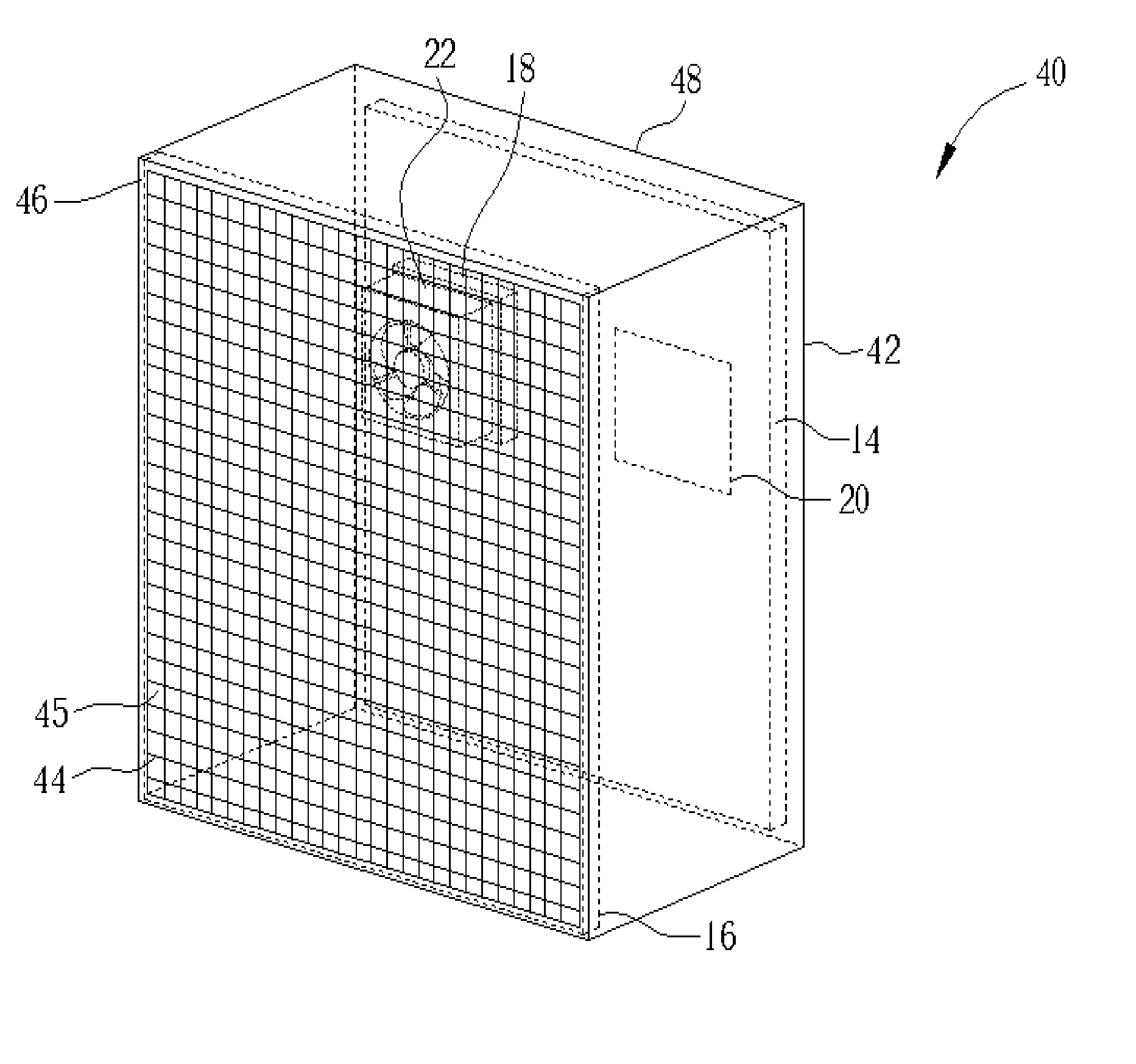
[0021]Please refer to FIG. 3 showing a perspective front view of an electronic apparatus 40 according to the present invention. The devices of the electronic apparatus 40 in FIG. 3 having the same numberings have the same name and function as those of the electronic apparatus 10 in FIG. 1, so that a further description is hereby omitted. The difference between the electronic apparatus 40 and the electronic apparatus 10 is that, the first side wall 24 with the holes 15 of the electronic apparatus 10 is replaced by a first side wall 46 with a metal net 44. A motherboard 14 may be installed on a second side wall 48, and the metal net 44 is required to contact to a housing 42 as well as the strings of the metal net 44 are required to contact each other in order to form a ground circuit to shield the electromagnetic wave generated by the electronic apparatus 40. The metal net 44 may be separated from the housing 42 or may adhere to the housing 42, while a transparent dust-proof member 16...

third embodiment

[0022]Please refer to FIG. 4 showing a perspective view of an electronic apparatus 50 according to the present invention. The devices of the electronic apparatus 50 in FIG. 4 having the same numberings have the same name and function as those of the electronic apparatus 10 in FIG. 1, so that a further description is hereby omitted. The difference between the electronic apparatus 50 and the electronic apparatus 10 is that, the electronic apparatus 50 includes a housing 52, a motherboard 14 may be installed on a second side wall 58, a first side wall 56 includes a plurality of holes 55, but a transparent dust-proof member 54 is installed in the holes 55. The transparent dust-proof member 54 is made of glass or plastic, which can be inserted in the holes 55 or separated from the holes 55 by a predetermined distance by adhering to the housing 52.


PUM


Abstract

An electronic apparatus includes a housing comprising a plurality of holes on a first side wall, a transparent dust-proof member installed on a side of the first side wall having the plurality of holes, a motherboard may be installed on a second side wall inside the housing having a processor installed on the motherboard inside the housing for processing programs and data and a memory for storing programs and data. The transparent member allows visual inspection of the interior of the housing. The plurality of holes provides electromagnetic shielding.

Description

BACKGROUND OF INVENTION[0001]1. Field of the Invention[0002]The present invention relates to an electronic apparatus, and more specifically, to an electronic apparatus with a housing for seeing inside.[0003]2. Description of the Prior Art[0004]An electronic apparatus comprises modules such as a central processing unit (CPU), a memory, an interface card, a hard disk drive, and a power supply. These modules are contained in a housing and communicate mutually via numerous electrical connections. The electronic signals of these modules and electrical connections have a high frequency, for instance, the frequency of a CPU is up to 1 GHz, thus electromagnetic radiation occurs. Electromagnetic radiation has an unfavorable influence on users and the environment, i.e. electromagnetic radiation interference, so that most countries and regions have set up standards for electromagnetic radiation. In order to prevent electromagnetic radiation, a typical computer housing is made of metal.[0005]Ad...

Claims


Application Information

Patent Timeline
Patent Type & Authority Patents(United States)
IPC IPC(8): G06F1/16G06F1/18H05K5/02H05K9/00
CPCG06F1/181H05K9/0041H05K5/0239H05K5/03
Inventor TAN, KO-CHEN
Owner MICRO-STAR INTERNATIONAL
Why Eureka
Try Eureka