Slotted multimode interference device

a multi-mode interference and interference device technology, applied in multiplex communication, instruments, optical elements, etc., can solve the problems of occupying more space on the integrated optical chip than is desirable, suffering high insertion loss, and still much longer than necessary or optimal

Inactive Publication Date: 2006-04-25
ARMY THE SEC OF THE UNITED STATES OF AMERICA AS REPRESENTED BY THE
View PDF6 Cites 22 Cited by
  • Summary
  • Abstract
  • Description
  • Claims
  • Application Information

AI Technical Summary

Benefits of technology

[0013]In view of the foregoing, an embodiment of the invention provides a multimode interference (MMI) device comprising at least one input port, at least one output port, a multimode interference region separating the input port from the output port, and at least one subregion in the multimode interference region, wherein a self-image length within the multimode interference region is reduced by a factor that is approximately equal to one p

Problems solved by technology

However, like all SCWP devices, multimode interference devices can be rather long (geometrically), and thus take up more space on the integrated optical chip than is desirable.
Conventional devices rely on bulk optical filters and therefore suffer high insertion loss.
While MMI SCWP devices generally outperform other competing conven

Method used


Image

  • Slotted multimode interference device
  • Slotted multimode interference device
  • Slotted multimode interference device

Examples


Embodiment Construction

[0045]The invention and the various features and advantageous details thereof are explained more fully with reference to the non-limiting embodiments that are illustrated in the accompanying drawings and detailed in the following description. It should be noted that the features illustrated in the drawings are not necessarily drawn to scale. Descriptions of well-known components and processing techniques are omitted so as to not unnecessarily obscure the invention. The examples used herein are intended merely to facilitate an understanding of ways in which the invention may be practiced and to further enable those of skill in the art to practice the invention. Accordingly, the examples should not be construed as limiting the scope of the invention.

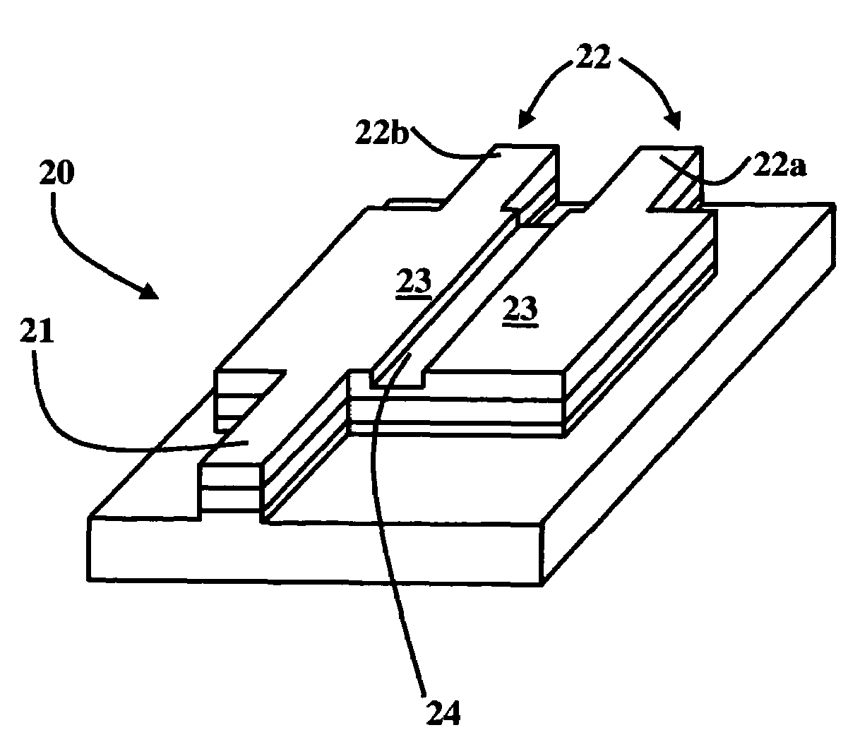
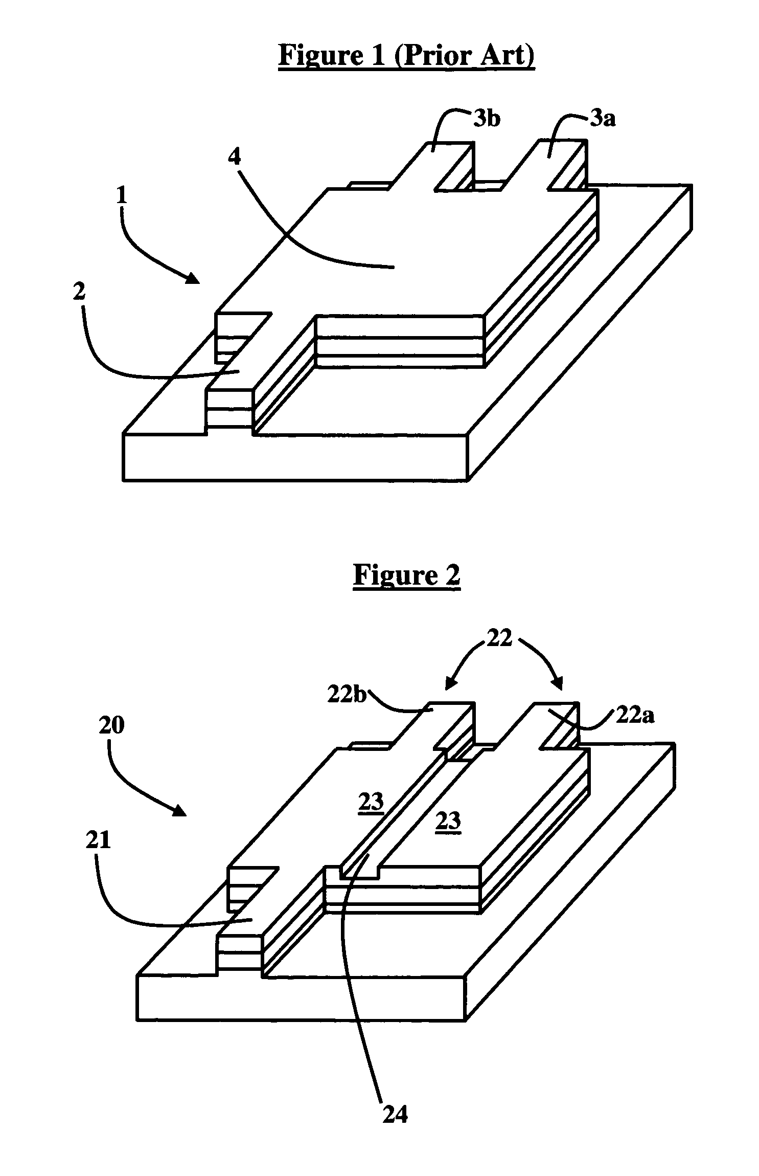
[0046]As previously mentioned, there is a need for an improved self-imaging waveguide device and a method of manufacturing the same. Referring now to the drawings, and more particularly to FIGS. 2 through 15, there are shown preferred embo...


PUM


Abstract

A multimode interference device and method of making the same comprises at least one input port, at least one output port, a multimode interference region separating the input port from the output port, and at least one subregion in the multimode interference region, wherein a self-image length within the multimode interference region is reduced by a factor that is approximately equal to one plus a number of subregions configured in the multimode interference region, wherein the at least one subregion is configured to have an effective width and effective refractive index running longitudinally through the multimode interference region. Additionally, the subregion may comprise at least one slot.

Description

GOVERNMENT INTEREST[0001]The invention described herein may be manufactured, used, and / or licensed by or for the United States Government.BACKGROUND OF THE INVENTION[0002]1. Field of the Invention[0003]The invention generally relates to integrated optical communications, and more particularly to a slotted multimode interference device for use in telecommunications, sensing, and related applications.[0004]2. Description of the Related Art[0005]Within this application several publications are referenced by Arabic numerals within brackets. Full citations for these publications may be found at the end of the specification immediately preceding the claims. The disclosures of all these publications in their entireties are hereby expressly incorporated by reference into the present application for the purposes of indicating the background of the invention and illustrating the general state of the art.[0006]Multimode interference (MMI) devices are useful for the separation and combination o...

Claims


Application Information

Patent Timeline
IPC IPC(8): G02B6/26
CPCG02B6/2813
Inventor MACKIE, DAVID M.
Owner ARMY THE SEC OF THE UNITED STATES OF AMERICA AS REPRESENTED BY THE
Why Eureka
Try Eureka