Optical performance monitor

a technology of optical performance monitor and optical spectrum analyzer, which is applied in the field of optical devices, can solve the problems of affecting the cost and reliability of the monitor, being subject to stringent industrial requirements, and being bulky and expensiv

Inactive Publication Date: 2006-04-25
LUMENTUM OPERATIONS LLC
View PDF14 Cites 27 Cited by
  • Summary
  • Abstract
  • Description
  • Claims
  • Application Information

AI Technical Summary

Problems solved by technology

Furthermore, they are generally bulky as well as costly.
Optical communication systems require industrial grade optical performance monitors (OPM), which function similarly to the traditional OSA, but are however subject to stringent industrial requirements.
Parallel acquisition of spectral data requires multiple photodetectors, which negatively affects cost and reliability of the monitor.
The respective disadvantages of the two approaches are exacerbated when higher wavelength resolution and a larger number of spectral points to be analyzed is required.
For example, both the size of the dispersive element and the number of photodiodes scale proportionally to the wavelength resolution, thereby increasing the size and cost of the device and reducing it reliability.
Similarly, higher wavelength resolution requires larger tunable filters and progressively more strict requirements on tuning filters wherein progressively finer tuning is required, complicating the control loops and affecting reproducibility issues.
However, they typically offer only limited frequency resolution with a limited, typically between 8 and 40, number of output channels, with a typical frequency spacing between output channels of ˜400 to 50 GHz.
Decreasing the frequency spacing further below 25 GHz requires progressively larger and more expensive devices, with increasing cost per monitored channel.

Method used


Image

  • Optical performance monitor
  • Optical performance monitor
  • Optical performance monitor

Examples


Embodiment Construction

[0058]Exemplary embodiments of an optical apparatus for monitoring an input optical signal are shown in FIG. 1 and FIGS. 3–8 and are hereafter described.

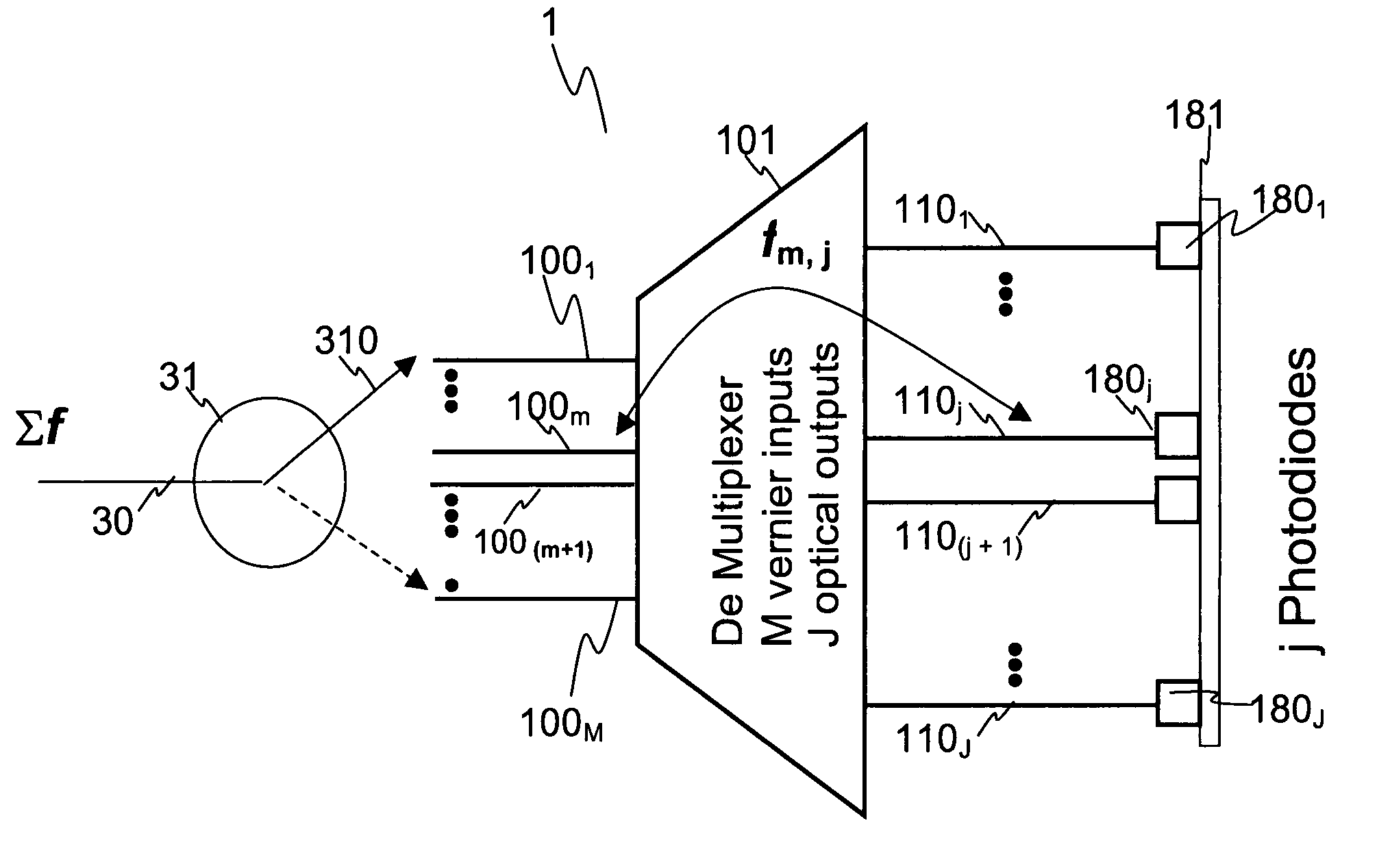
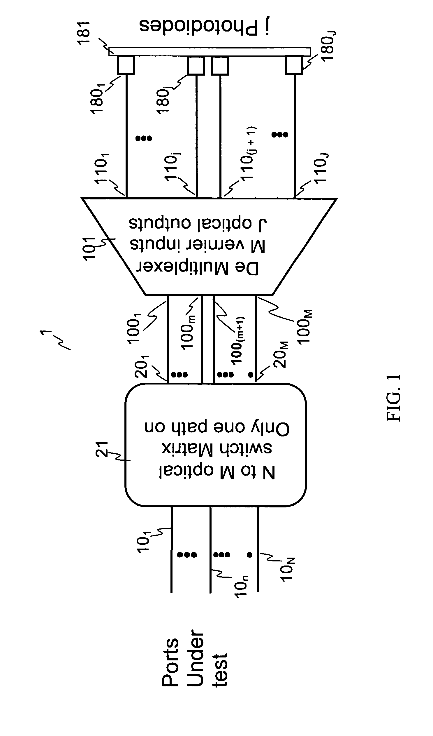
[0059]With reference to FIG. 1, an apparatus 1 for monitoring an input optical signal at a first plurality of K distinct optical frequencies, K>1, has a dispersive element 101 disposed between N×M switching means 21 and monitoring means 181. The N×M optical switching means 21 hereafter are also referred to simply as switch 21, which can be embodied as an N×M optical switch matrix, or in other ways, examples of which will be described later in this specification. The switch 21 has N optical input ports 101 to 10N and M optical output ports 201 to 20M and has a functionality of controllably providing optical coupling between any input port to any one output port. The dispersive element 101 has M input ports 1001 to 100M, each of which is optically coupled to a different output port of the switch 21. The monitoring means 181 are prefer...


PUM


Abstract

An apparatus for monitoring an input optical signal at a plurality of distinct optical frequencies is disclosed wherein a demultiplexing arrayed waveguide grating (AWG) having a plurality of M>1 Vernier input ports is disposed between an optical switch and a photodiode array coupled to the output ports of the AWG. In operation, the optical switch sequentially provides the input optical signal into each of the Vernier ports, and signals detected by photodiodes are stored in a memory unit. The apparatus is capable of monitoring the input optical signal with a frequency step which is M times smaller than a frequency spacing between the AWG transmission bands, and obtain M frequency-resolved readings from each photodiode.

Description

CROSS-REFERENCE TO RELATED APPLICATIONS[0001]This application claims priority of U.S. Provisional Patent Application No. 60 / 489,545 filed Jul. 23, 2003, entitled “Optical Channel Monitor with Integrated Arrayed Waveguides”, which is incorporated herein by reference for all purposes.FIELD OF THE INVENTION[0002]The present invention generally relates to optical devices, and more particularly relates to optical performance monitors and optical spectrum analyzers for optical communications.BACKGROUND OF THE INVENTION[0003]Optical communication systems employing wavelength division multiplexed (WDM) technology achieve large transmission capacity by spacing optical channels as closely as possible, typically less than a nanometer (nm) apart. As the channel spacing decreases, monitoring spectral characteristics of the channels becomes more critical in verifying system functionality, identifying performance drift, and isolating system faults. For example, such monitoring is critical in detec...

Claims


Application Information

Patent Timeline
Patent Type & Authority Patents(United States)
IPC IPC(8): G02B6/28H04B10/00G02B6/26
CPCH04B10/0795G02B6/12019
Inventor SHEN, JINXIMCLEOD, ROBERT R.CRAFTS, DOUGLAS E.FONDEUR, BARTHELEMYDING, YONGSUN, PANG-CHEN
Owner LUMENTUM OPERATIONS LLC
Why Eureka
Try Eureka