
Method and apparatus for intelligent noise reduction in a distributed communication system

Inactive Publication Date: 2006-04-25
COMMSCOPE TECH LLC
View PDF4 Cites 110 Cited by
  • Summary
  • Abstract
  • Description
  • Claims
  • Application Information

AI Technical Summary

Benefits of technology

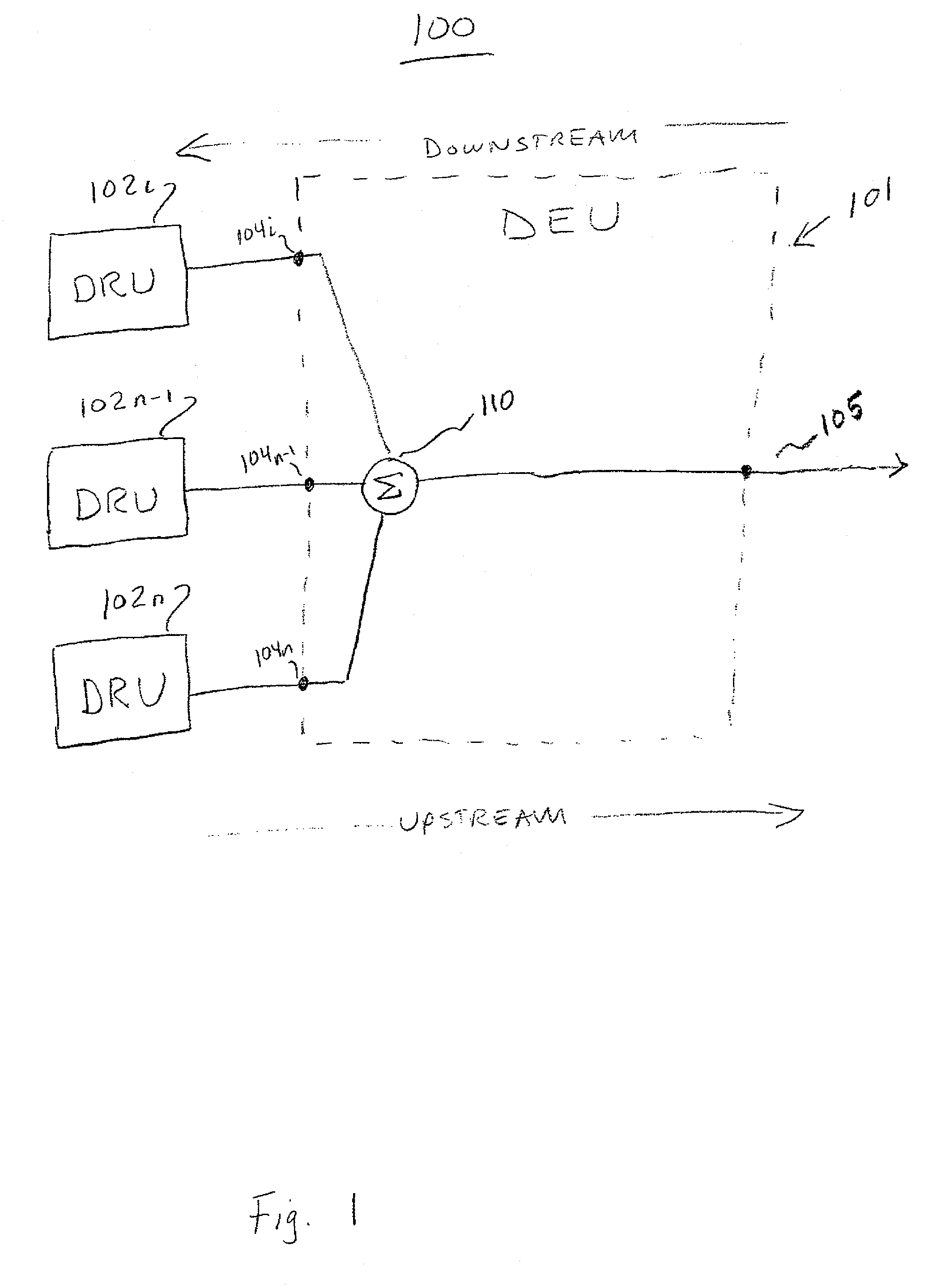
[0009]FIG. 1 is an illustration of a representative system 100 for distribution of wireless signals in a difficult environment for wireless signal propagation, such as in a large building or enclosure. Embodiments of the present invention are not limited to wireless signal propagation in and around buildings or other enclosures but are applicable to enhanced wireless systems for any appropriate coverage area. While wireless systems typically provide bi-directional communications, embodiments of the present invention provide enhanced upstream signal handling.
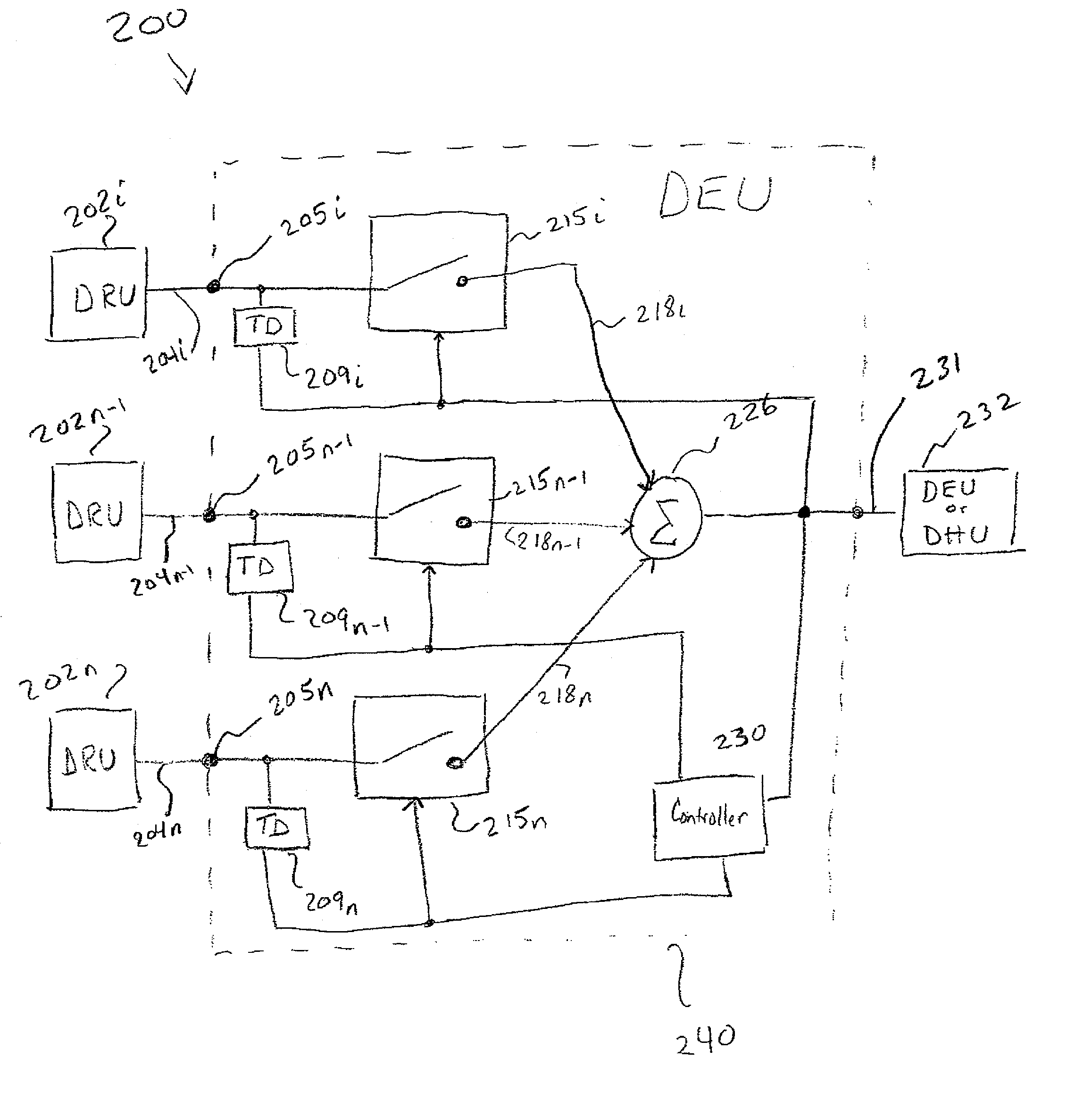
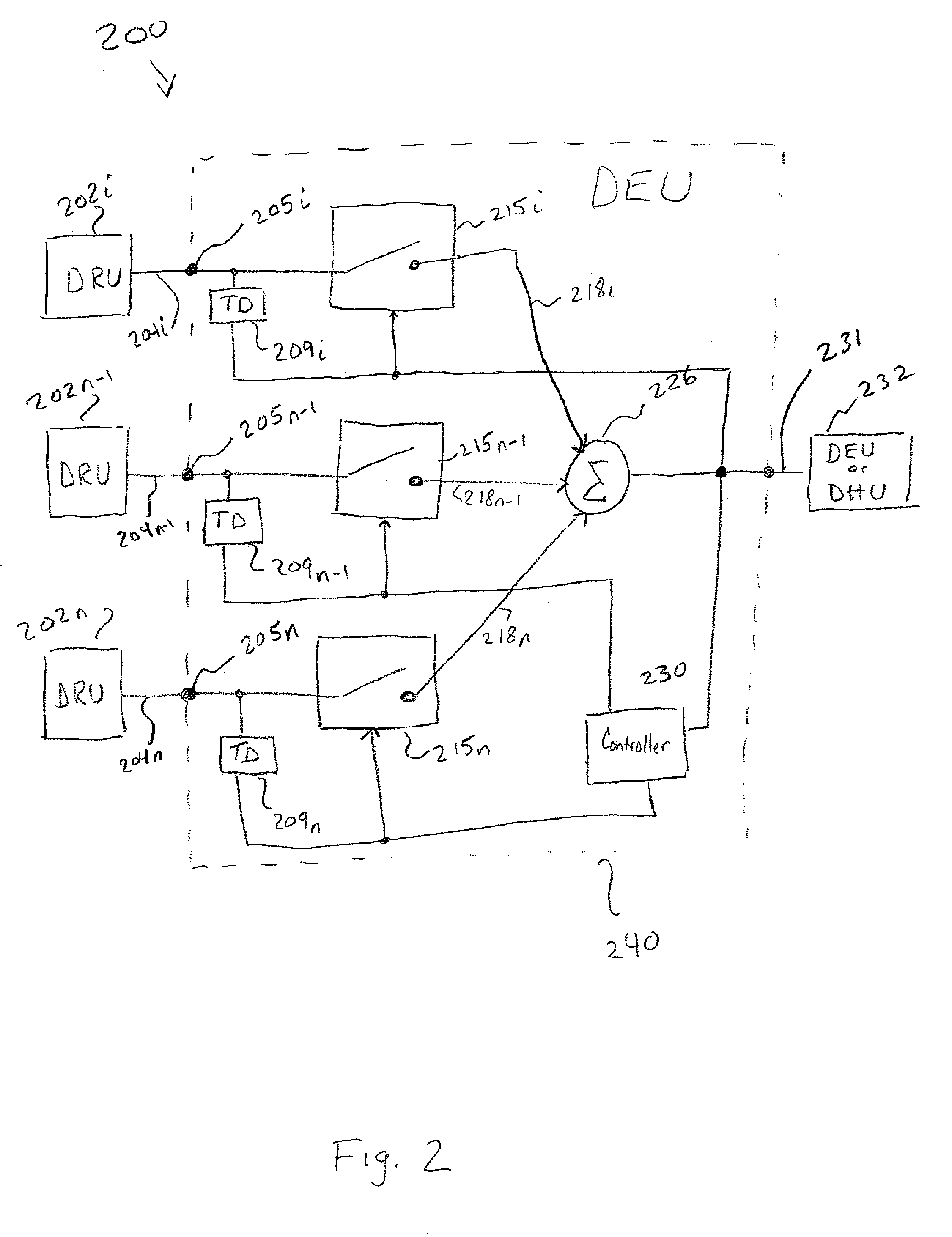
[0015]System 300 includes a digital host unit (DHU) 306, which interfaces with a wireless network 305 via a wireless interface device (WID) 307. DHU 306 is coupled to the public switched telephone network (PSTN), or a mobile telecommunications switching office (MTSO) or other switching office / network. DEU 308 is situated between the DHU 306 and one or more DRUs. In the forward path, DEU 308 expands the coverage area by splitting signals received from DHU 306 to a plurality of DRUs 304. In the reverse path, DEU 308 receives signals from a plurality of DRUs 304, sums the signals together and transports them to a DHU 306 or another DEU such as DEU 308. The system allows for successive branching of signals using DEUs 308 and expanded coverage to multiple DRUs 304.

Problems solved by technology

The operational range of a system that combines and distributes signals within buildings or other areas where wireless signal propagation is likely to be a problem, whether the signals are digital or analog or some combination of both, is limited by the dynamic range handling capability of the system.
Background noise effectively limits the dynamic range of a system.
The problem is exacerbated when signals are combined from RF receivers that each have a given noise figure and the combined signals may contain aliases, images and spurs of the background noise due to sampling effects, frequency translation and the like.
If such signals are combined in a purely additive way without regard to whether any useful information is present, the overall noise performance of the system will suffer.

Method used


Image

  • Method and apparatus for intelligent noise reduction in a distributed communication system
  • Method and apparatus for intelligent noise reduction in a distributed communication system
  • Method and apparatus for intelligent noise reduction in a distributed communication system

Examples


Embodiment Construction

[0008]In the following detailed description of the preferred embodiments, reference is made to the accompanying drawings that form a part hereof, and in which are shown by way of illustration specific embodiments in which the invention may be practiced. It is to be understood that other embodiments may be utilized and structural changes may be made without departing from the scope of the present invention.

[0009]FIG. 1 is an illustration of a representative system 100 for distribution of wireless signals in a difficult environment for wireless signal propagation, such as in a large building or enclosure. Embodiments of the present invention are not limited to wireless signal propagation in and around buildings or other enclosures but are applicable to enhanced wireless systems for any appropriate coverage area. While wireless systems typically provide bi-directional communications, embodiments of the present invention provide enhanced upstream signal handling.

[0010]The system 100 inc...


PUM


Abstract

A wireless distribution system includes a number of remote units distributed in a coverage area to receive wireless signals and to provide the signals through the distribution system to input ports of an expansion unit where the signals are combined, detectors operatively connected to one or more of the plurality of input ports to determine the presence of information carrying signals at the input ports, a number of selection circuits to select signals in which information has been detected, and a node to combine the selected signals.

Description

TECHNICAL FIELD[0001]The present invention is related to a distributed communications system, and more particularly to a method and apparatus for noise reduction in a distributed communication system that may be implemented in a multipoint-to-point communication system in which wireless (radio frequency or otherwise) signals are distributed in buildings or other areas where wireless signal propagation is likely to be a problem.BACKGROUND INFORMATION[0002]The operational range of a system that combines and distributes signals within buildings or other areas where wireless signal propagation is likely to be a problem, whether the signals are digital or analog or some combination of both, is limited by the dynamic range handling capability of the system. Background noise effectively limits the dynamic range of a system. In a distributed system, such as the one disclosed in U.S. patent application Ser. No. 09 / 619,431, “Point-To-Point Digital Radio Frequency Transport,” filed on Jul. 19,...

Claims


Application Information

Patent Timeline
IPC IPC(8): H04B1/38H04H20/00H04B7/005H04B7/08
CPCH04W52/42H04B7/0837
Inventor SOLUM, JEFFREY
Owner COMMSCOPE TECH LLC
Learn More