Method And Apparatus For Using An Accelerometer Signal To Detect Misfiring In An Internal Combustion Engine

an accelerometer and internal combustion engine technology, applied in engine ignition, structural/machine measurement, analog and hybrid computing, etc., can solve the problems of engine misfire, engine power and performance reduction, inefficient engine operation, etc., and achieve the effect of improving the robustness of the method

Active Publication Date: 2010-11-11
WESTPORT FUEL SYST CANADA INC
View PDF11 Cites 30 Cited by
  • Summary
  • Abstract
  • Description
  • Claims
  • Application Information

AI Technical Summary

Benefits of technology

[0007]The preferred method further comprises converting the filtered signal data set to absolute values prior to integrating it. This keeps the integrated values positive and amplifies the effect of the integration, which is a calculation of the area under the plot of the filtered signal data set. That is, whereas a plot of filtered signal data has on its vertical axis the filtered signal voltage, the plot of the integrated signal data has on its vertical axis the integration of the filtered signal voltage which is the area under the plot of the filtered signal voltage against time, here measured in crank angle degrees. Because the area is cumulative this magnifies the difference between signal noise and the signal associated with combustion, which enables the disclosed method to accurately detect engine misfire.
[0008]The preferred method can also further comprise subtracting a motoring component from the filtered signal data set before integrating it. This reduces the range of amplitude in the data and facilitates signal processing. To further reduce the data that needs to be processed, the method preferably further comprises sampling the real-time accelerometer signal for only a predetermined portion of the engine cycle that corresponds to when combustion occurs.
[0010]The method preferably further comprises retrieving the predetermined reference data set from a look-up table. The predetermined reference data set can be stored and retrieved based on the engine speed and load. That is, engine speed and load can be the parameters that define the operating point that is associated with the predetermined reference data set and which is also associated with the real-time accelerometer signal. The data stored in the look-up table can be generated by a calibration engine which is the same model and specification as the engine from which the real-time accelerometer signal data set is collected. A calibration engine can have more instrumentation to confirm whether the engine is firing or misfiring, so that the predetermined reference data set is confirmed to be associated with either when the engine is firing or when it is misfiring. It does not matter which engine condition, (firing or misfiring), is associated with the predetermined reference data set, as long as the engine condition associated with the predetermined reference data set is known, so that firing or misfiring can be determined by comparing the integrated signal data set to the predetermined reference data set.
[0013]To further improve the robustness of the method, the method can further comprise rejecting a determination that misfire has occurred if a secondary indicator of firing indicates that the engine did fire. By cross-checking with a secondary indicator, false, or uncertain, determinations of misfire are rejected.
[0016]The real-time accelerometer signal is typically transmitted from the accelerometer sensor as an analogue signal. The electronic controller can digitize the real-time accelerometer signal by sampling from this signal with a predetermined frequency that provides the resolution needed to detect misfiring and any other combustion characteristics that are determined from the accelerometer signal.
[0019]As with the described method, the electronic controller can be programmed to detect engine misfire by using one of the above described techniques for comparing the integrated signal data set to the predetermined reference data set. The electronic controller can also be programmed to count the number of misfires and to limit engine operation or signal an operator when the number of misfires counted exceeds a predetermined number. In addition to improve the robustness of the method the electronic controller can be programmed to reject a determination that misfire has occurred if a secondary indicator of firing indicates that the engine did fire.

Problems solved by technology

Engine misfire occurs when charge delivered to an engine's combustion chamber fails to ignite.
Misfire can be a symptom of unstable engine operating conditions and can cause inefficient engine operation, reduced engine power and performance, and high emissions of unburned fuel.
There can be a number of different causes for engine misfire, such as reduced compression, which can be caused by worn piston rings, a failed head gasket, a worn crankshaft, intake or exhaust valves that are not seating properly.
Another cause for engine misfire relates to the fuel injection system, for example, if the fuel injector is broken or not working properly to introduce the required amount of fuel.
If the engine uses exhaust gas recirculation, the valve that controls the amount of exhaust gas that is recirculated could be broken or stuck, so that too much exhaust gas is recirculated.
If an engine uses oxygen sensors or mass flow sensors to control the fuel air mixture the failure of one of these sensors could cause misfire.
Engines that use an ignition assist, such as a spark-plug in Otto Cycle engines or a glow plug in Diesel Cycle engines, could misfire if the ignition assist device or the controls for timing or energizing the ignition assist device fails.
Engine knock correlates to violent combustion events that can be caused by pre-mature and uncontrolled detonation of the charge inside the combustion chamber, caused, for example, if an Otto-Cycle engine has been fuelled with a fuel with too low an octane rating, or if spark timing is too advanced, or if deposits in a combustion chamber create hot spots that cause early ignition.
In a Diesel-Cycle engine, engine knock can be caused, for example, if fuel injection timing is too early.
Engine knock can cause a decrease in engine performance and in severe cases, if not corrected, engine knock can cause serious damage to the engine, including destruction of the pistons, connecting rods, exhaust valves, head gasket and spark plugs or glow plugs.
However, from such an accelerometer signal it can be difficult to detect engine misfire under all operating conditions.
However, at low load conditions and when the engine is idling, the amplitude of the deflections of the engine component where the accelerometer sensor is installed is much less compared to when under high load conditions, so the amplitude of the accelerometer signal is also lower.
With lower signal amplitudes associated with combustion events under low load and idle conditions it can be difficult to detect misfire if there is signal noise in the accelerometer signal.
Signal noise is unavoidable because the component to which the accelerometer sensor is mounted is also deflected by other effects such as, for example, engine vibration, road “noise” caused by uneven road conditions when the engine is installed in a vehicle, and deflections caused by the operation of other mechanical devices attached to the engine.
While some signal noise can be filtered out, it can still be difficult to detect misfire, or the absence of combustion, since some signal noise inevitably remains in the filtered signal, and the amplitude of the signal noise can be difficult to distinguish from the signal component that is caused by the engine firing.

Method used


Image

  • Method And Apparatus For Using An Accelerometer Signal To Detect Misfiring In An Internal Combustion Engine
  • Method And Apparatus For Using An Accelerometer Signal To Detect Misfiring In An Internal Combustion Engine
  • Method And Apparatus For Using An Accelerometer Signal To Detect Misfiring In An Internal Combustion Engine

Examples


Embodiment Construction

)

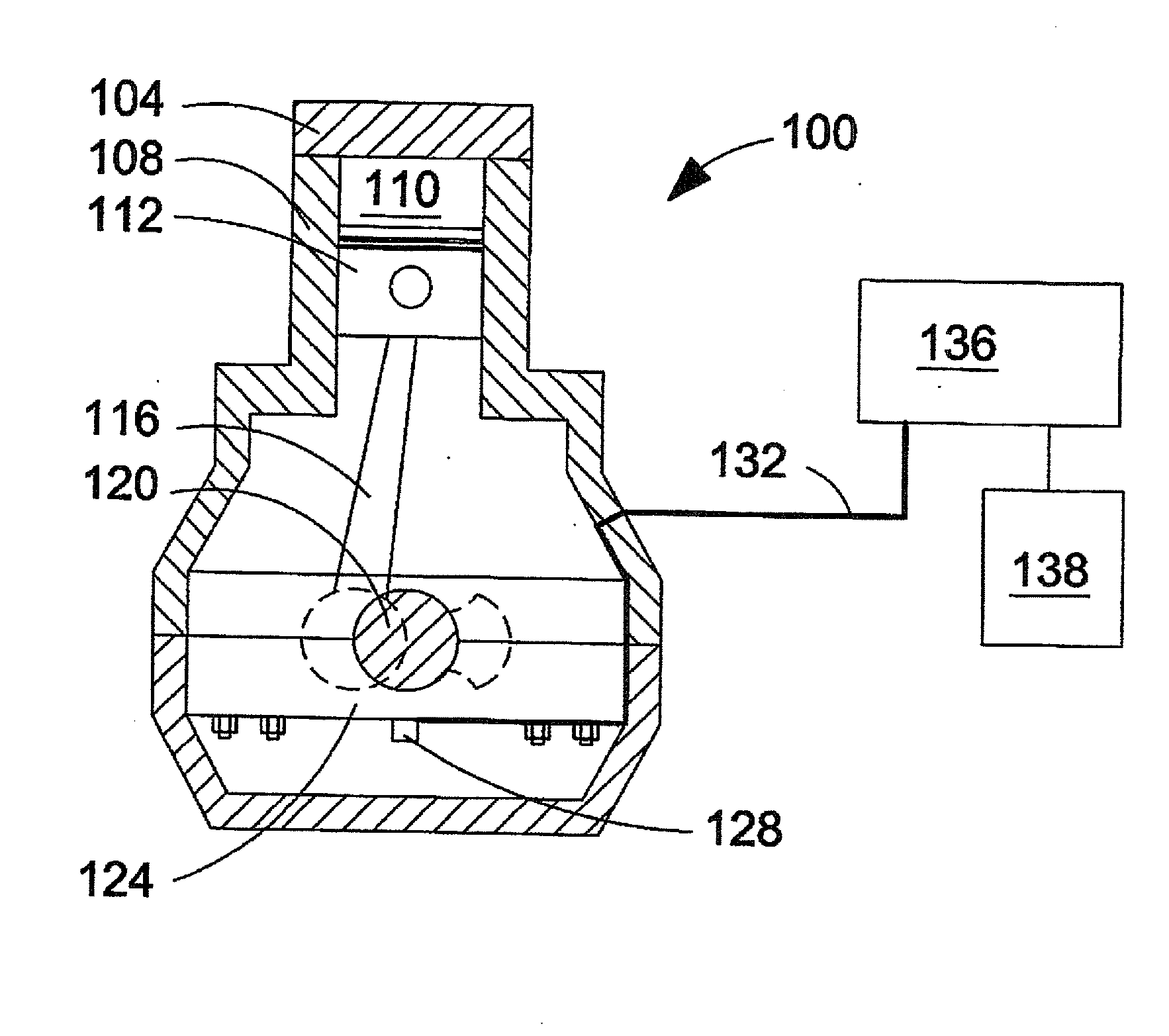
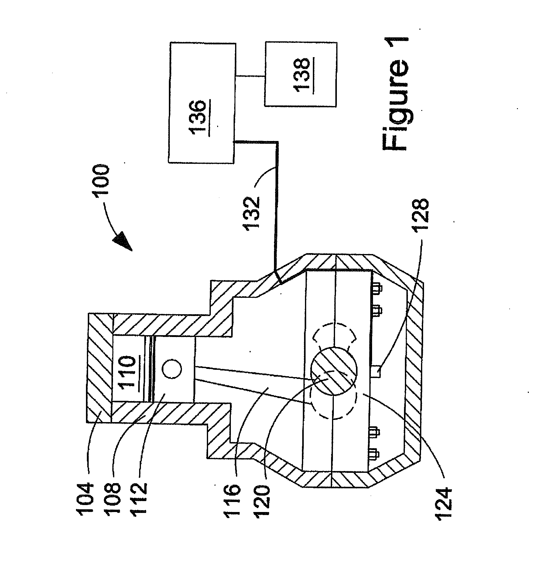
[0025]FIG. 1, shows by way of example, an internal combustion engine with a control system that can be used to detect misfiring from an accelerometer signal. Engine 100 includes combustion chamber 110, which in this example is defined by cylinder 108, cylinder head 104 and piston 112. For simplicity, only one combustion chamber is shown although persons skilled in the technology will understand that the engine typically has two or more cylinders, and when there is a plurality of cylinders they can be arranged in banks. Piston 112 is reciprocable within cylinder 108, and the reciprocating motion of piston 112 is translated into rotation of crankshaft 120 via connecting rod 116 which is operatively attached at opposite ends to piston 112 and crankshaft 120. Intake and exhaust valves (not shown) operate to deliver charge comprising oxygen from an intake manifold to combustion chamber 110, and to remove exhaust by-products therefrom to an exhaust manifold. Engine 100 further comprises ...


PUM


Abstract

The method comprises operating an engine and collecting a real-time accelerometer signal from an accelerometer sensor. The real-time accelerometer signal is digitized and filtered to isolate data in a frequency range associated with combustion to produce a filtered signal data set. The filtered signal data set is integrated to produce an integrated signal data set, and misfire is detected by comparing the integrated signal data set with a predetermined reference data set associated with the same operating point. The apparatus is a control system for an engine that comprises an accelerometer sensor mounted to the engine; a look-up table in which is stored predetermined reference data sets, in association with predetermined operating conditions; and an electronic controller programmed to carry out the foregoing method.

Description

CROSS-REFERENCE TO RELATED APPLICATIONS[0001]This application is a continuation of International Application No. PCT / CA2008 / 002085, having an international filing date of Nov. 27, 2008, entitled “Method And Apparatus For Using An Accelerometer Signal To Detect Misfiring In An Internal Combustion Engine”. The '085 international application claimed priority benefits, in turn, from Canadian Patent Application No. 2,610,388 filed Nov. 29, 2007. The '085 international application is hereby incorporated by reference herein in its entirety.FIELD OF THE INVENTION[0002]The present invention relates to a method and apparatus for using an accelerometer signal to detect misfiring in an internal combustion engine.BACKGROUND OF THE INVENTION[0003]Engine misfire occurs when charge delivered to an engine's combustion chamber fails to ignite. Misfire can be a symptom of unstable engine operating conditions and can cause inefficient engine operation, reduced engine power and performance, and high emi...

Claims


Application Information

Patent Timeline
Patent Type & Authority Applications(United States)
IPC IPC(8): F02D28/00G01M15/11
CPCF02D41/1498F02D2200/1012F02D35/027G01M15/11F02D2200/1015
Inventor HUANG, JIANCHEUNG, DURANMUMFORD, DAVID
Owner WESTPORT FUEL SYST CANADA INC
Why Eureka
Try Eureka