Color solid-state image capturing apparatus and electronic information device

a technology of solid-state image and electronic information device, which is applied in the direction of instruments, television systems, and scanning details of television systems, can solve problems such as inability to deal, and achieve the effects of suppressing color shading, increasing size, and uniform imag

Active Publication Date: 2009-05-21
SHARP KK
View PDF2 Cites 30 Cited by
  • Summary
  • Abstract
  • Description
  • Claims
  • Application Information

AI Technical Summary

Benefits of technology

[0048]Further, according to a specific color arrangement of color filters, such as Bayer arrangement, an influence to adjacent Gr pixels on the left and right is significant in the left and right edge sections of the light receiving surface of the image capturing area and the color signal intensity of the Gb pixel decreases, and an influence to adjacent Gb pixels on the top and bottom is significant in the upper and lower edge sections of the light receiving surface of the image capturing area and the color signal intensity of the Gr pixel decreases, thereby causing an unbalance to the green color of “Gr” and “Gb”, which are supposed to be equal. However, a correction is made by successively or incrementally increasing the size (or light focusing ratio; the size being a diameter or area) of a microlens corresponding to the Gb pixel color filter of a green color among a plurality of color filters as the position shifts from the center section of the light receiving surface of the image capturing area to the left or right edge portion in a horizontal direction (row direction or transverse direction) as well as successively or incrementally increasing the size (or light focusing ratio; the size being a diameter or area) of a microlens corresponding to the Gr pixel color filter of a green color among the plurality of color filters as the position shifts from the center section of the light receiving surface of the image capturing area to the upper edge or lower edge portion in a perpendicular direction (column direction or longitudinal direction). As a result, a color shading caused by a specific color arrangement of color filters is corrected, thereby obtaining a uniform image.
[0049]When a specific shape, namely a color shading of Fij (x, y) occurs, it is possible to correct the color shading by changing the size of the microlens to the size in proportion to 1 / Fij (x, y). As a result, the color shading is suppressed.
[0050]It is an effective condition for preventing the color shading to arrange a plurality of light receiving sections each in the same area in a plan view with equal pitch in a horizontal direction as well as a perpendicular direction.
[0051]When the color signals are of three primary colors of R, G and B, signal processing in the following steps will be easier compared to a color arrangement of complementary colors. In addition, when it is Bayer arrangement, the unit color signals will be R, B, Gb and Gr, and therefore, the G color occupies half of the color arrangement, thereby obtaining high color resolution.
[0052]When each microlens has a partially spherical shape, such a spherical shape has a higher light focusing efficiency of a microlens compared to other lens shapes. Therefore, it is possible to prevent the decrease of the light focusing ratio due to the variation in size of the microlens.
[0053]According to the present invention with the configuration described above, a fixed period of a plurality of color filters is defined as a unit. A size (or light receiving ratio; in proportion to diameter or area) of a plurality of microlenses is variable for each light receiving section such that the ratio of a plurality of color signals will be constant within the unit. As a result, the color shading phenomenon of a specific shape, which is caused by various factors such as the positioning of the infrared cut filter and the specific color arrangement of color filters, can be suppressed.

Problems solved by technology

However, such a configuration is not able to deal with the positioning of the infrared rays cut filter 104 formed by a dielectric multilayer film, according to Reference 1 described above, or the color shading phenomenon caused by a specific color arrangement of color filters, or such a configuration is not intended to deal with such color shading phenomenon.

Method used


Image

  • Color solid-state image capturing apparatus and electronic information device
  • Color solid-state image capturing apparatus and electronic information device
  • Color solid-state image capturing apparatus and electronic information device

Examples


embodiment 1

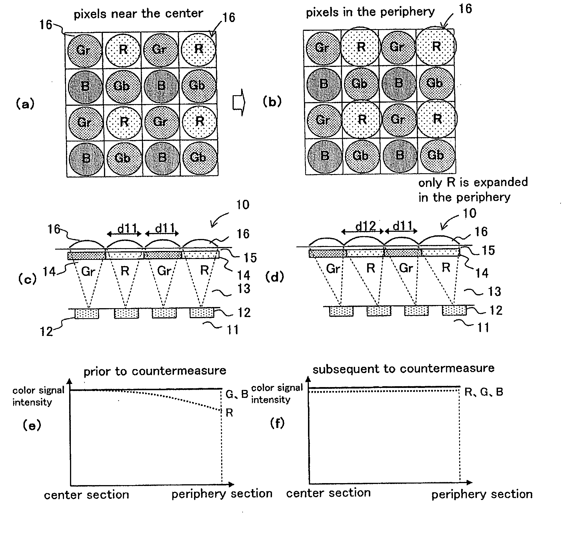
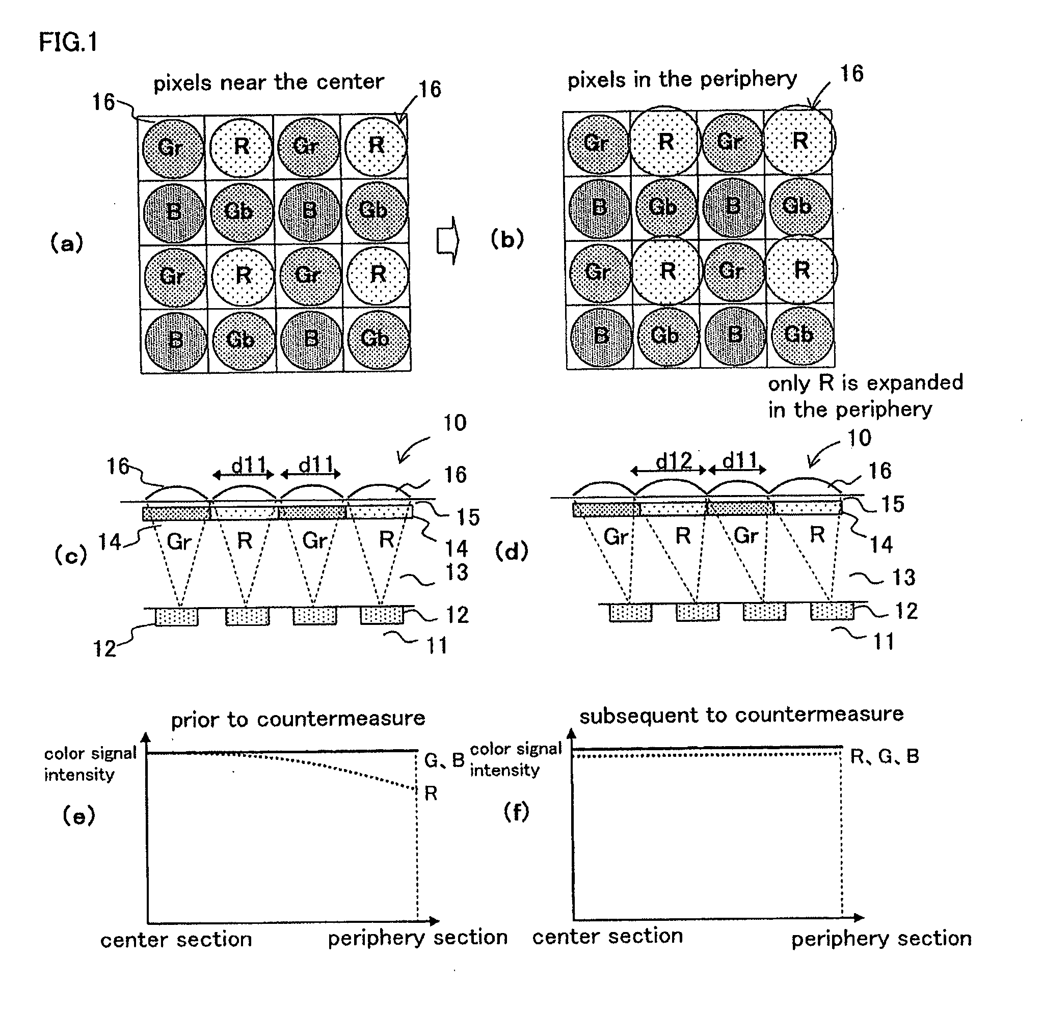
[0080]FIG. 1(a) is a plan view of microlenses corresponding to respective colors near the center section of a light receiving surface as an exemplary essential configuration of Embodiment 1 of the color solid-state image capturing apparatus according to the present invention. FIG. 1(b) is a plan view of microlenses corresponding to respective colors near the periphery section of the light receiving surface. FIG. 1(c) is a longitudinal cross sectional view in a horizontal direction of FIG. 1(a). FIG. 1(d) is a longitudinal cross sectional view in a horizontal direction of FIG. 1(b). FIG. 1(e) is a distribution chart of a color signal intensity prior to the countermeasure according to Embodiment 1. FIG. 1(f) is a distribution chart of a color signal intensity subsequent to the countermeasure according to Embodiment 1.

[0081]In FIGS. 1(a) to 1(d), a color solid-state image capturing apparatus 10 according to Embodiment 1 is provided with a plurality of photoelectric conversion sections ...

embodiment 2

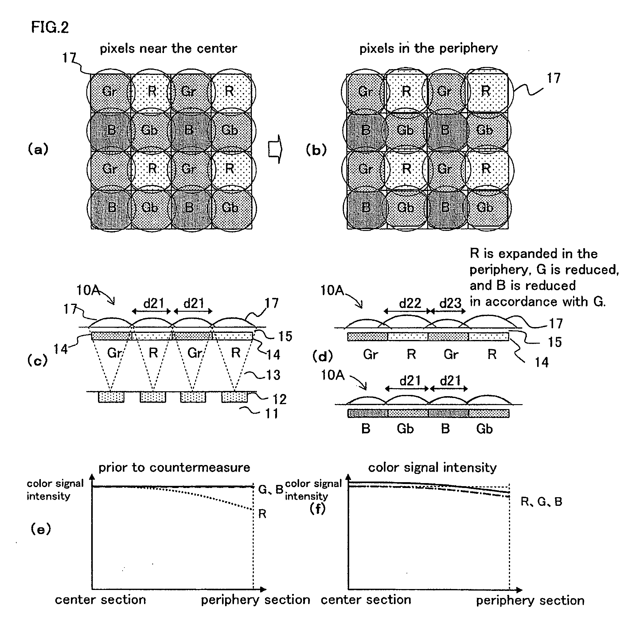
[0086]FIG. 2 is a plan view of microlenses corresponding to respective colors near the center section of the light receiving surface as an exemplary essential configuration of Embodiment 2 of the color solid-state image capturing apparatus of the present invention. FIG. 2(b) is a plan view of microlenses corresponding to respective colors near the periphery section of the light receiving surface. FIG. 2(c) is a longitudinal cross sectional view of FIG. 2(a) in a horizontal direction. FIG. 2(d) is a longitudinal cross-sectional view of FIG. 2(b) in a horizontal direction. FIG. 2(e) is a distribution chart of a color signal intensity prior to the countermeasure according to Embodiment 2. FIG. 2(f) is a distribution chart of a color signal intensity subsequent to the countermeasure according to Embodiment 2.

[0087]In FIGS. 2(a) to 2(d), a color solid-state image capturing apparatus 10A according to Embodiment 2 is provided with a plurality of photoelectric conversion sections 12 (light ...

embodiment 3

[0089]In Embodiments 1 and 2 described above, it has been described that the size of the microlens for the light receiving surface is expanded as the position moves further away from the center section to the periphery section of the light receiving surface of the image capturing area in order to improve the fact that the infrared cut wavelength of a dielectric multilayer film shifts towards the short wavelength side as the incident angle of light increases and the color signal of the R pixel decreases in the periphery section of the light receiving surface of the image capturing area. In Embodiment 3, a case will be described where, in order to improve the fact that a color signal intensity of a Gb pixel decreases in the left and right edge sections of the light receiving surface of the image capturing area and a color signal intensity of a Gr pixel decreases in the upper and lower edge sections of the light receiving surface of the image capturing area in a specific color arrangem...


PUM


Abstract

A color solid-state image capturing apparatus is provided, where a plurality of light receiving sections are arranged on a light receiving surface of an image capturing area, a plurality of color filters are positioned in a constant period above the plurality of light receiving sections, and a plurality of microlenses for focusing light on the plurality of respective light receiving sections are positioned on the plurality of color filters, and a plurality of color signals are output in accordance with the plurality of color filters, where the constant period of the plurality of color filters is defined as a unit, and the size of the plurality of microlenses is variable for each light receiving section so that the ratio of the plurality of color signals is constant in the unit.

Description

[0001]This nonprovisional application claims priority under 35 U.S.C. §119(a) to Patent Application No. 2007-256195 filed in Japan on Sep. 28, 2007, the entire contents of which are hereby incorporated by reference.BACKGROUND OF THE INVENTION[0002]1. Field of the Invention[0003]The present invention relates to a color solid-state image capturing apparatus having a photoelectric conversion section (which is defined as a light receiving section corresponding to each pixel) configured with a semiconductor element (photodiode), which performs photoelectric conversions on and capturing incident light from a subject for each pixel, and a plurality of microlenses for focusing incident light through corresponding color filters of respective colors on corresponding light receiving sections; and an electronic information device, such as a digital camera (e.g., digital video camera and digital still camera), an image input camera, a scanner, a facsimile machine, and a camera-equipped cell phon...

Claims


Application Information

Patent Timeline
Patent Type & Authority Applications(United States)
IPC IPC(8): H04N5/335H01L27/14H04N9/07H04N101/00
CPCG02B5/201H01L27/14621H01L27/14627H04N9/045H04N5/23212H04N5/357H04N5/2254H01L27/14605H04N25/60H04N25/134
Inventor WATANABE, TAKASHI
Owner SHARP KK
Why Eureka
Try Eureka