Eureka AIR delivers breakthrough ideas for toughest innovation challenges, trusted by R&D personnel around the world.

Illuminating unit and projection-type image display apparatus employing the same

a technology of projection-type image and illumination unit, which is applied in lighting and heating apparatus, television systems, instruments, etc., can solve the problems of difficult to realize compact illumination unit, difficult to make collimated beam using illumination unit, and large beam spot produced by conventional illumination unit that is not suitable for projection-type image display apparatus. , to achieve the effect of reducing the overall size of the unit and improving the collimation characteristics of the beam

Inactive Publication Date: 2006-02-02
SAMSUNG ELECTRONICS CO LTD
View PDF11 Cites 16 Cited by
  • Summary
  • Abstract
  • Description
  • Claims
  • Application Information

AI Technical Summary

Benefits of technology

[0010] The present general inventive concept provides an illuminating unit with a compact design which is capable of improving collimating characteristics of beams emitted from a plurality of light sources positioned at different locations within the illuminating unit. The present general inventive concept also provides a projection-type image display apparatus designed to provide uniform images and to reduce an overall size thereof by employing the illuminating unit having the compact design.

Problems solved by technology

However, it is difficult to make the collimated beam using the illuminating unit.
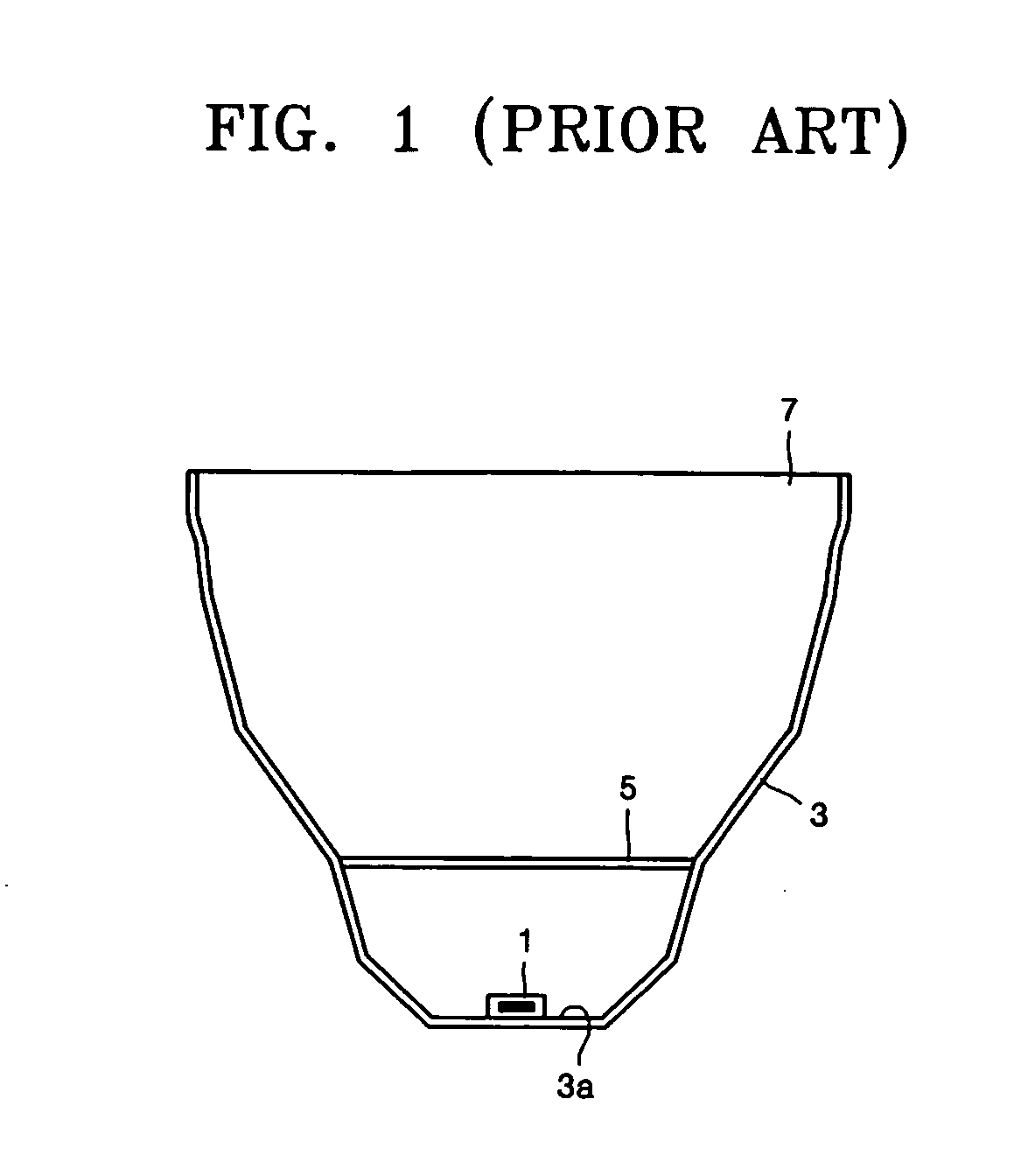
However, since the conventional illuminating unit having a polygonal reflector has a limitation on reducing its size, a beam spot produced by the conventional illuminating unit has a diameter that is not suitable for use in a projection-type image display apparatus.
Another drawback exists in that it is difficult to realize a compact illuminating unit, since there is a limitation in reducing the size of a reflector.

Method used


Image

  • Illuminating unit and projection-type image display apparatus employing the same
  • Illuminating unit and projection-type image display apparatus employing the same
  • Illuminating unit and projection-type image display apparatus employing the same

Examples


Embodiment Construction

[0019] Reference will now be made in detail to the embodiments of the present general inventive concept, examples of which are illustrated in the accompanying drawings, wherein like reference numerals refer to the like elements throughout. The embodiments are described below in order to explain the present general inventive concept while referring to the figures.

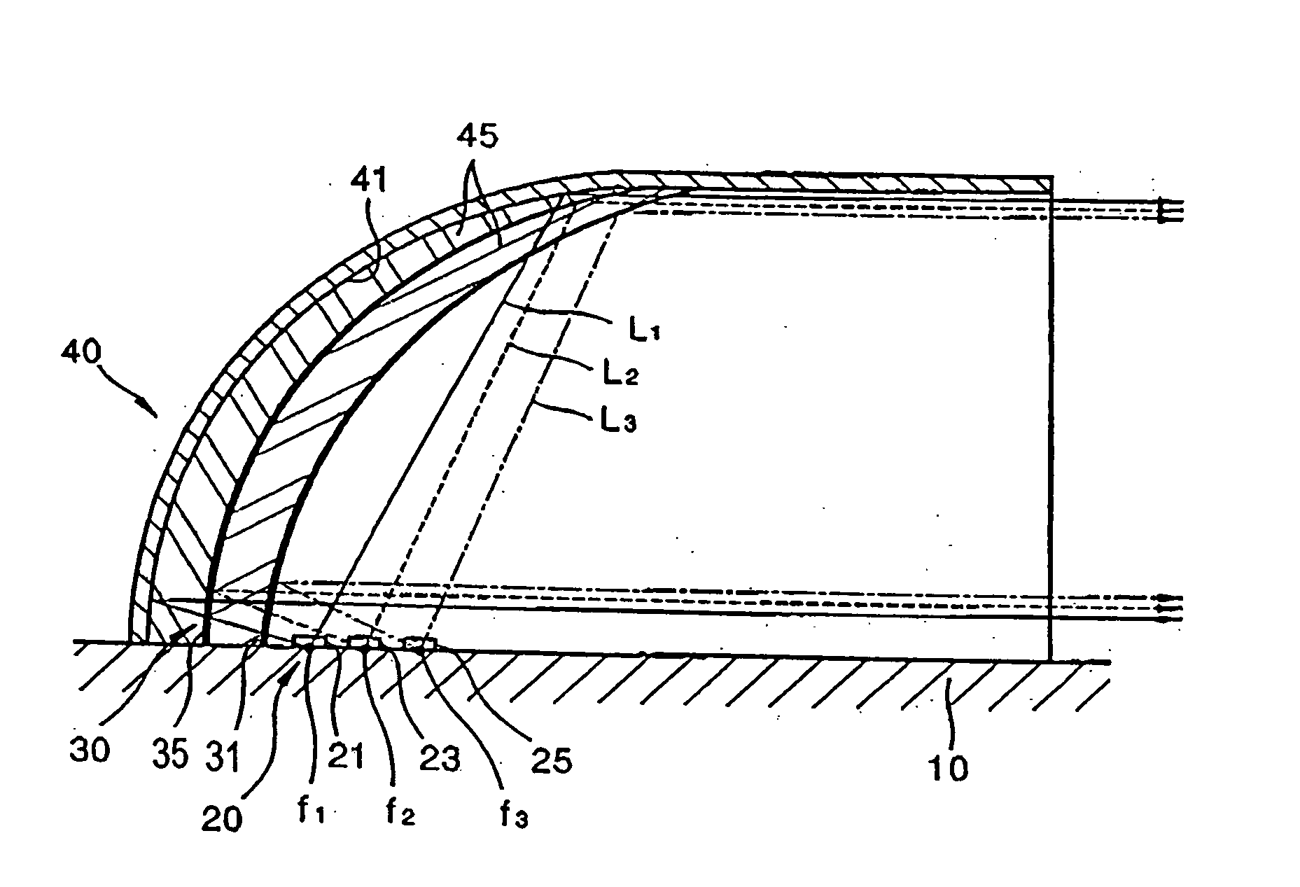
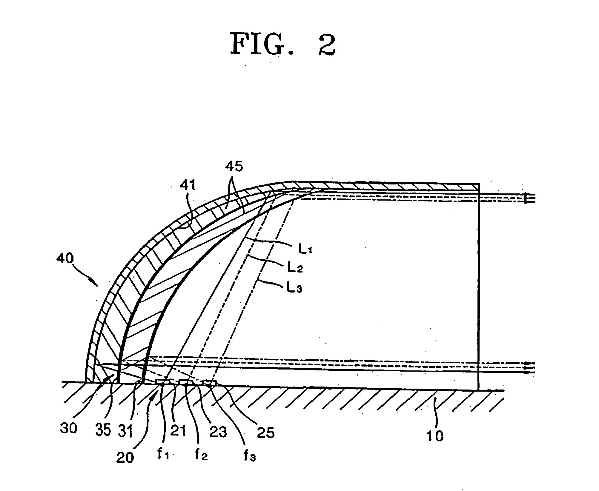
[0020] Referring to FIG. 2, an illuminating unit according to an embodiment of the present general inventive concept includes a base 10, a plurality of light sources 20 that produce and emit a plurality of beams of different wavelength bands, and a color filter 30 that selectively reflects the plurality of beams according to wavelength band such that the reflected beams propagate in a first direction.

[0021] The plurality of light sources 20 may be organic light-emitting diodes (OLEDs) or LEDs made from semiconductor compounds and include first, second, and third light sources 21, 23, and 25 installed at different positions...


PUM


Abstract

An illuminating unit with a compact design which is capable of improving collimating characteristics of beams emitted from a plurality of light sources positioned at different locations, and a projection-type image display apparatus employing the illuminating unit. The illuminating unit includes a base, a plurality of light sources that are positioned at different locations on the base to emit beams of different wavelength bands, and at least one color filter with a predetermined curvature to reflect one or more beams of predetermined wavelengths from among the beams emitted by the plurality of light sources such that the reflected one or more beams propagate in a first direction and to pass one or more remaining beams of other wavelength bands. In the illuminating unit, the beams of different wavelength bands emitted by the plurality of light sources are combined to emit a combination of these beams in the first direction. The projection-type image display apparatus includes the illuminating unit, an optical integrator to receive a collimated beam from the illuminating unit and to make a uniform therefrom, an image-forming system to receive the uniform beam from the optical integrator and to produce an image by selectively reflecting the uniform beam, a beam splitter disposed in an optical path between the illuminating unit and the image-forming system to change the optical path of incident beams such that a beam incident from the illuminating unit is directed toward the image-forming system while a beam incident from the image-forming system is directed toward a screen, and a projection lens unit disposed adjacent to the beam splitter opposite the image-forming system to enlarge the image produced by the image-forming system and to project the enlarged image onto the screen.

Description

CROSS-REFERENCE TO RELATED APPLICATIONS [0001] This application claims priority from Korean Patent Application No. 2004-58800, filed on Jul. 27, 2004, in the Korean Intellectual Property Office, the disclosure of which is incorporated herein in its entirety by reference. BACKGROUND OF THE INVENTION [0002] 1. Field of the Invention [0003] The present general inventive concept relates to an illuminating unit to produce and emit a beam and a projection-type image display apparatus employing the same, and more particularly, to an illuminating unit with a compact design which is capable of improving collimating characteristics of beams emitted by a plurality of light sources at different locations within the illuminating unit, and a projection-type image display apparatus employing the same. [0004] 2. Description of the Related Art [0005] In general, an illuminating unit including a non-point light source, such as light-emitting diodes (LEDs), and a reflector with a single curvature is u...

Claims


Application Information

Patent Timeline
Patent Type & Authority Applications(United States)
IPC IPC(8): F21V9/00
CPCG02B5/04G02B26/0833G02B27/1033G02B27/126G03B21/208H04N5/74H04N5/7416H04N9/315G02B27/148G02B27/18
Inventor LEE, KYE-HOONKIM, DAE-SIK
Owner SAMSUNG ELECTRONICS CO LTD
Why Eureka
Eureka Blog
Learn More