Sole construction for energy storage and rebound

a technology of energy storage and rebound, which is applied in the field of footwear articles, can solve the problems of participant foot and ankle system loss, thirty percent, and typical shoe design failure to adequately address the needs of the participant's foot and ankle system

Inactive Publication Date: 2006-05-02
NEWTON RUNNING CO INC
View PDF65 Cites 31 Cited by
  • Summary
  • Abstract
  • Description
  • Claims
  • Application Information

AI Technical Summary

Benefits of technology

[0020]It is an object of the present invention to provide a new and useful sole construction that may be incorporated into footwear or used as an insert into existing footwear.

Problems solved by technology

Typical shoe designs fail to adequately address the needs of the participant's foot and ankle system during each of these successive stages.
Typical shoe designs cause the participant's foot and ankle system to lose a significant proportion, by some estimates at least thirty percent, of its functional abilities including its abilities to absorb shock, load musculature and tendon systems, and to propel the runner's body forward.
This is because the soles of current walking and running shoe designs fail to address individually the muscles and tendons of a participant's foot.
The failure to individually address these foot components inhibits the flexibility of the foot and ankle system, interferes with the timing necessary to optimally load the foot and ankle system, and interrupts the smooth and continuous transfer of energy from the heel to the toes of the foot during the three successive basic phases of the “on the ground” foot travel.
Traditional shoe construction, however, has failed to address this need.
Furthermore, midsole and sole compression, historically speaking, can be very destabilizing.
Another perplexing problem for shoe engineers has been how to store energy as the foot and ankle system rolls laterally to medially.
These rotational forces have been very difficult to absorb and control.
No past shoe designs, including the specific ones cited above, are believed to adequately address the aforementioned needs of the participant's foot and ankle system during walking and running activities in a manner that augments performance.
However, among the problems with the Snow embodiments is that they teach very thick soles comprised of tall cleats, a resilient membrane, deep apertures, and “guide plates.” The combination of these components is undesirable because they make up a very heavy shoe.
Furthermore, Snow shows numerous small parts that would be cost prohibitive to manufacture.
These numerous small cleats cannot affect enough rubber molecules through the resilient membrane to provide a competitive efficiency gain without increasing the thickness of the membrane to the point of impracticability.
Moreover, it takes a longer period of time for Snow's cleats to “cycle,” i.e., penetrate and rebound.
This produces a limiting effect for performance and efficiency gain potential.
Snow also fails to provide appropriate points of leverage for specific bone structures of the foot, control over the intrinsic rotational involvement of the foot and ankle system, bio-mechanical guidance, and the ability to produce tunable vertical vectors and transfer energy forward and rearward from heel, midfoot, forefoot and toes and vice-versa.

Method used


Image

  • Sole construction for energy storage and rebound
  • Sole construction for energy storage and rebound
  • Sole construction for energy storage and rebound

Examples


first exemplary embodiment

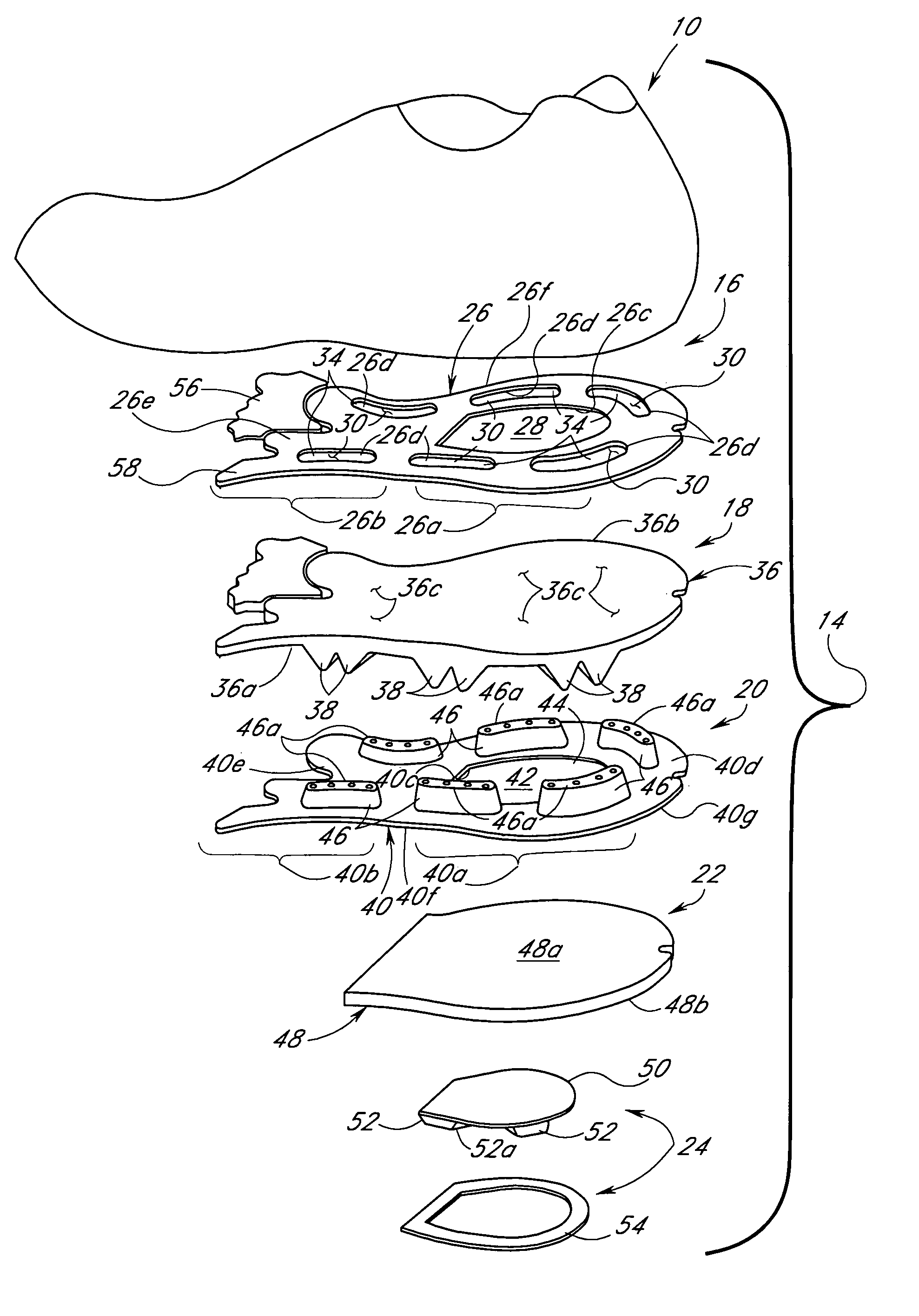
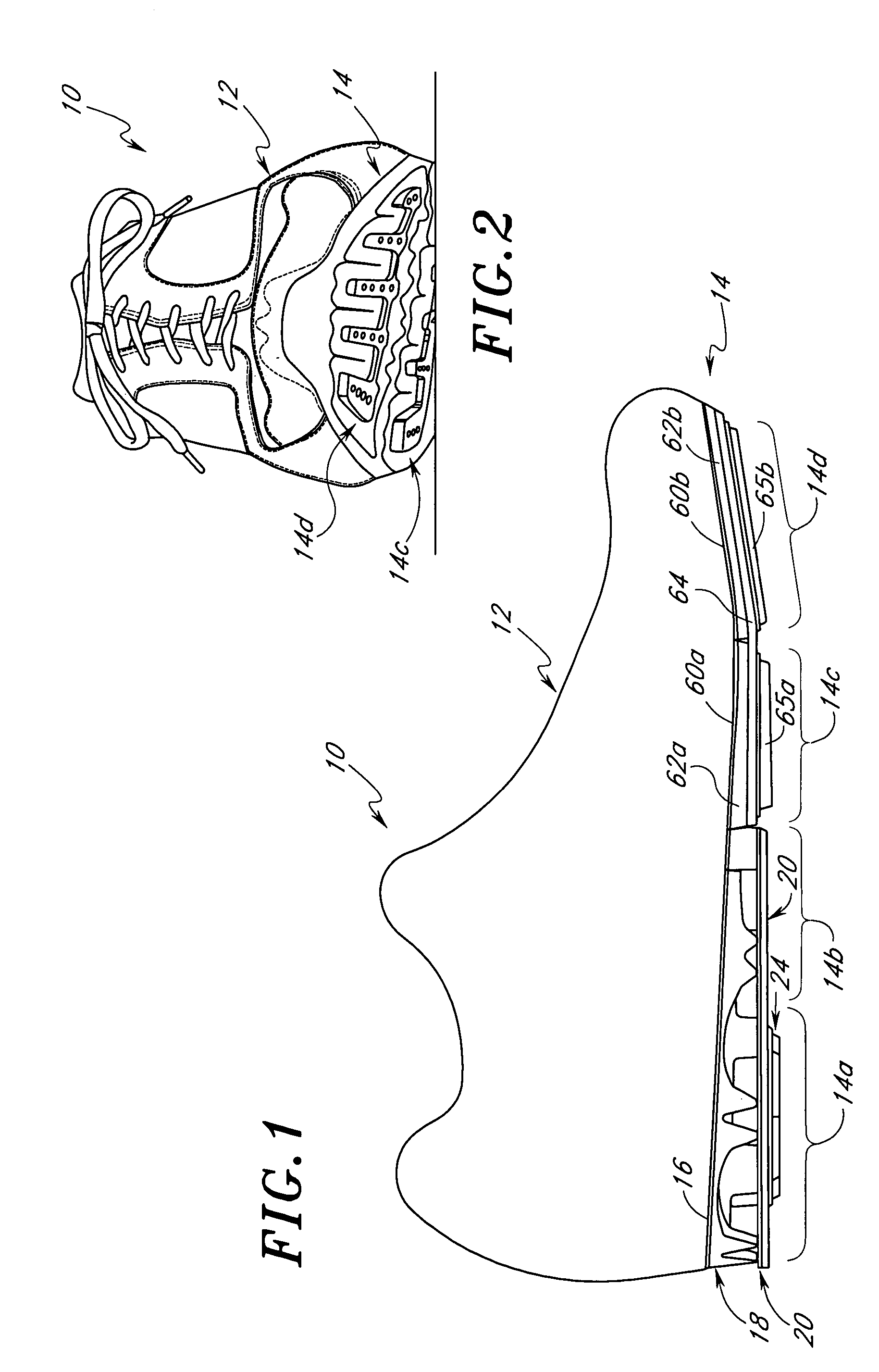
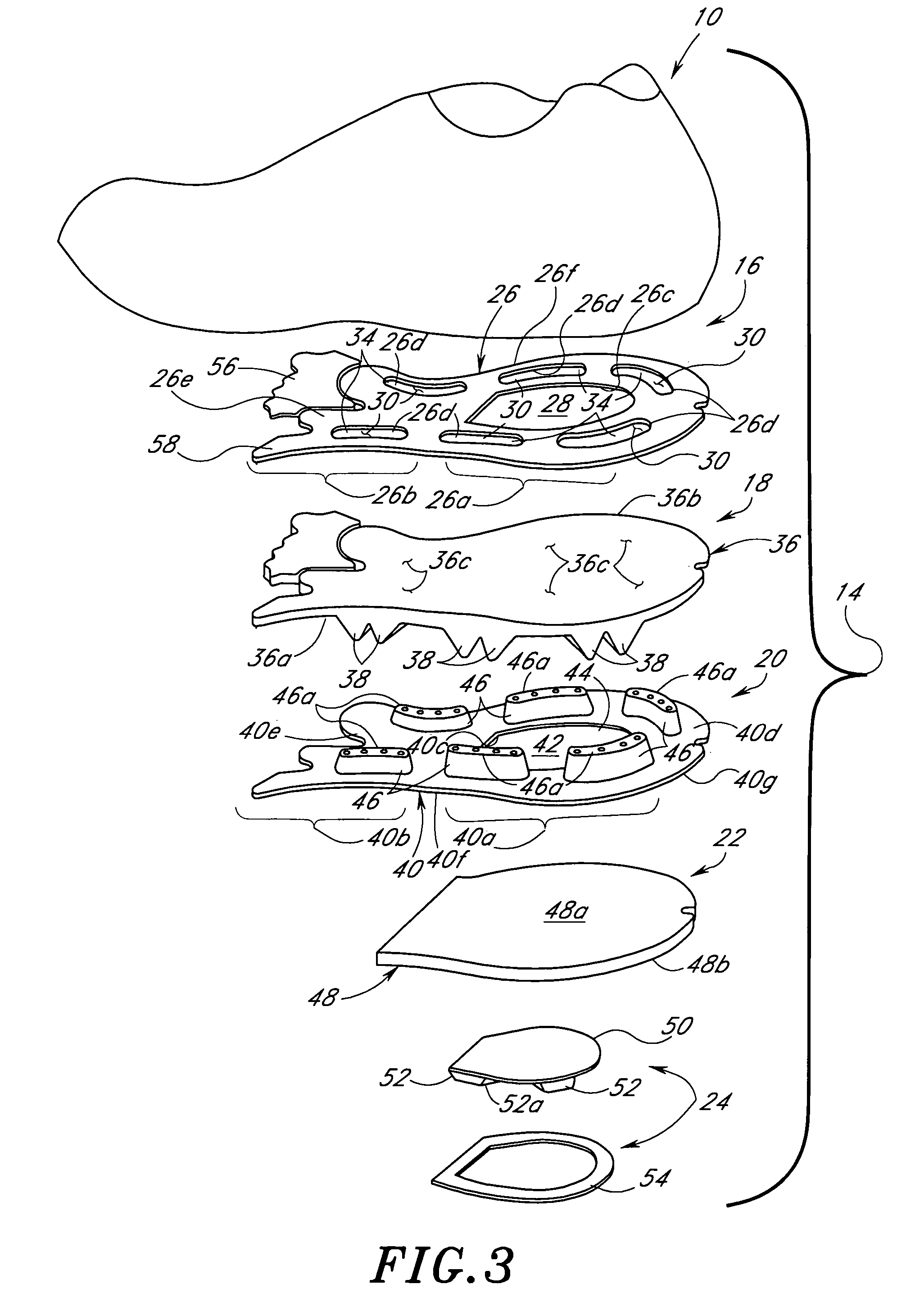
[0152]Referring to the drawings and particularly to FIGS. 1 and 2, there is illustrated a first exemplary embodiment of an article of athletic footwear for walking, running and / or jumping, being generally designated 10. The footwear 10 includes an upper 12 and a sole 14 having heel and midfoot regions 14A, 14B and metatarsal and toe regions 14C, 14D wherein are provided the structural features of the sole 14 constituting the present invention. The sole 14 incorporating the construction of the present invention improves the walking, running and jumping performance of a wearer of the footwear 10 by providing a combination of structural features which complements and augments, rather than resists, the natural flexing actions of the muscles of the foot to more efficiently utilize the muscular energy of the wearer.

[0153]Referring to FIGS. 1 and 3 to 8, the heel and midfoot regions 14A, 14B of the sole 14 basically includes the stacked combination of a footbed layer 16, an upper stretch l...

second exemplary embodiment

[0177]In a second exemplary embodiment, the present invention is directed to articles of footwear incorporating a sole either as an integral part thereof or as an insert wherein the sole is constructed so as to absorb, store and release energy during active use. Thus, it should be appreciated that the invention includes such a sole, whether alone, as an insert for an existing article of footwear or incorporated as an improvement into an article of footwear. In any event, the sole is adapted to be worn on the foot of a person while traversing along a support surface and is operative to store and release energy resulting from compressive forces between the person and the support surface.

[0178]With reference first to FIGS. 12–14, the second exemplary embodiment of the present invention is shown to illustrate its most simple construction. As may be seen in FIG. 1, an article of footwear in the form of an athletic shoe 110 has an upper 112 and a sole 114. Sole 114 includes a heel portion...

third exemplary embodiment

[0182]The simple structure shown in FIGS. 12–14 can be expanded to make a highly active sole, such as that shown in the third exemplary embodiment of the FIGS. 15–22. With reference to FIG. 15, it may be seen that an article of footwear in the form of an athletic shoe 150 has an upper 152 and a sole 154 with sole 154 being constructed according to the third exemplary embodiment of the present invention. Sole 154 includes a heel portion 156, a metatarsal portion 158 and a toe portion 160, all described below in greater detail. Thus, when reference is made to a “sole” it may be just one of these portions, a group of portions or a piece that underlies the entire foot or a portion thereof.

[0183]Turning first, then, to heel portion 156, the structure of the same may best be shown with reference to FIGS. 17–19. In these figures, it may be seen that heel portion 156 includes a first profile 162 formed by an annular heel plate 164 that has a plurality of spaced apart auxiliary actuator elem...


PUM


Abstract

A sole construction for supporting at least a portion of a human foot and for providing energy storage and return is provided. The sole construction includes a generally horizontal layer of stretchable material, at least one chamber positioned adjacent a first side of the layer, and at least one actuator positioned adjacent a second side of the layer vertically aligned with a corresponding chamber. Each actuator has a footprint size smaller than that of the corresponding chamber, and is sized and arranged to provide individual support to the bones of the human foot. The support structure when compressed causes the actuator to push against the layer and move the layer at least partially into the corresponding chamber. In one embodiment, the horizontal layer of stretchable material is at least partially enclosed by a wall the prevents horizontal displacement of the layer during compression.

Description

CROSS-REFERENCE TO RELATED APPLICATIONS[0001]This application is a continuation of U.S. application Ser. No. 10 / 004,533 filed Dec. 3, 2001, now abandoned and is related to and claims the benefit of U.S. Provisional Application No. 60 / 250,545, filed Dec. 1, 2000.BACKGROUND OF THE INVENTION[0002]1. Field of the Invention[0003]The present invention generally relates to articles of footwear, and more particularly, to a sole construction that may be incorporated into athletic footwear or as an insert into existing footwear and the like in order to store kinetic energy generated by a person. The sole construction has a combination of structural features enabling enhanced storage, retrieval and guidance of wearer muscle energy that complement and augment performance of participants in recreational and sports activities.[0004]2. Description of the Related Art[0005]From the earliest times when humans began wearing coverings on their feet, there has been an ever present desire to make such co...

Claims


Application Information

Patent Timeline
Patent Type & Authority Patents(United States)
IPC IPC(8): A43B7/06A43B7/32A43B13/12A43B13/18A43B13/24
CPCA43B7/1415A43B13/12A43B13/24A43B13/185A43B13/181
Inventor RUSSELL, BRIAN A.
Owner NEWTON RUNNING CO INC
Why Eureka
Try Eureka