Hole punch quick-change die assembly with pin strap and positioning system
What is Al technical title?
Al technical title is built by PatSnap Al team. It summarizes the technical point description of the patent document.
a technology of pin strap and positioning system, which is applied in the field of automatic paper hole punches to achieve the effect of simple and quick change, and easy backed out from the pin retainer
Inactive Publication Date: 2006-05-02
PERFORMANCE DESIGN LLC
View PDF58 Cites 10 Cited by
Summary
Abstract
Description
Claims
Application Information
AI Technical Summary
This helps you quickly interpret patents by identifying the three key elements:
Problems solved by technology
Method used
Benefits of technology
[0012]The invented punch machine also comprises an improved push-bar system for driving the die assembly. The push-bar is slidably supported in the punch machine, preferably by bushings in the side plates of the machine housing. Thus, the push-bar stays in place when the die assembly is removed, so that the die assembly may easily be reinserted without manually moving and aligning the die assembly and push-bar.
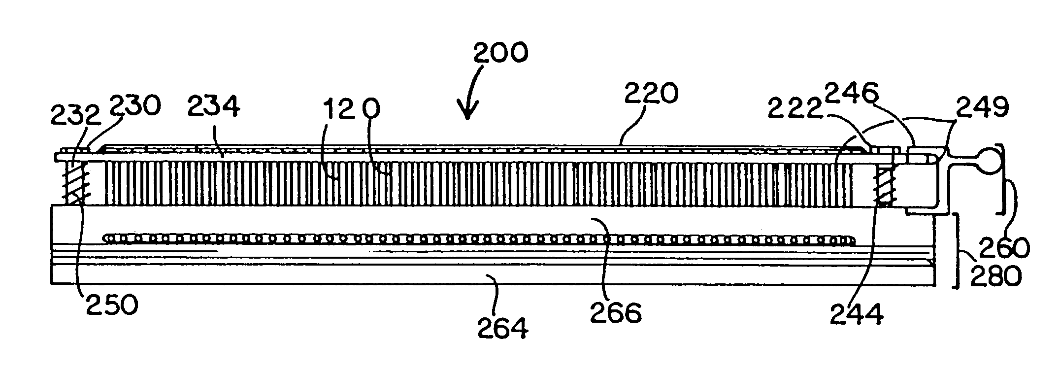
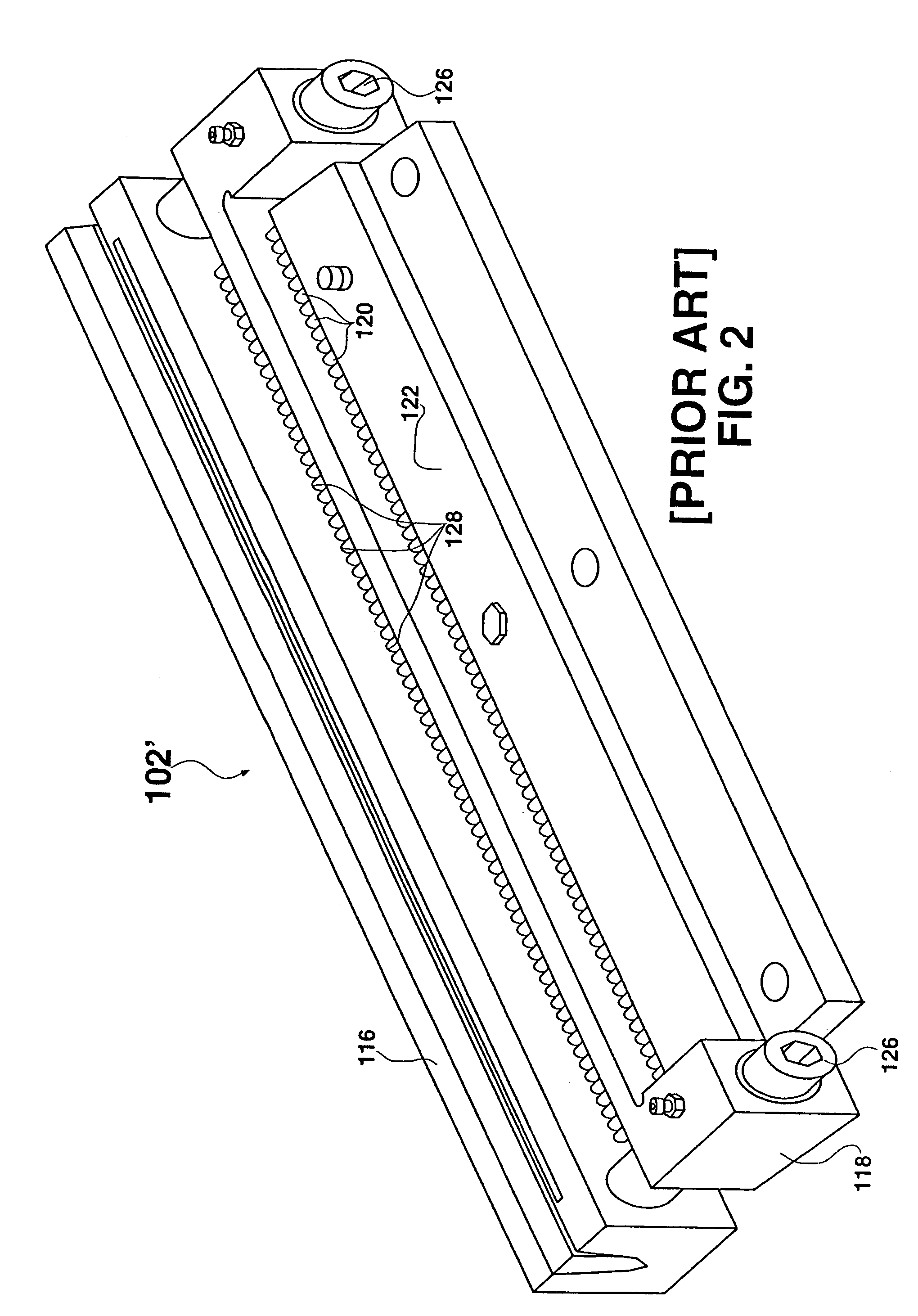
[0014]The die and pin retainer need not be bolted together or connected by any bushings or stripping bolts. However, in the especially-preferred embodiment, the invented positioning system includes a connecting mechanism for connecting the pin retainer to the die, so that the pin retainer will not fall away from the die. The positioning system preferably holds the pin retainer at the desirable distance from the die during handling and installation. The positioning system may be designed to bias the pin retainer out from the die at a set distance (that is, the “biased position”), which is the distance that is proper for the die assembly to slide smoothly into the machine, with the pin retainer sliding into the push-bar slot and the die sliding into proper clamping position. The positioning system with its biasing system is adapted so that, once the die assembly is installed, it does not interfere with forward and rearward movement of the pin retainer and pins during punching. The positioning system may also be adapted to include a floating feature that allows some leeway in the biased position of the pin retainer (and in the position of the associated apparatus that must slide through the push-bar slot), thus compensating for possible variations in the push-bar location at the time of installation of the die assembly. For example, this leeway may be necessary if wear and / or variations in punch machine construction result in the punch bar being slightly forward or rearward from its “standard” position when the push-bar operation is stopped. The leeway lets the pin retainer, pin heads, pin strap, and connecting mechanism move to match up with the location of the push-bar slot and smoothly slide into place.
[0015]The quick-change die assembly also provides a simplified and quick method of changing or rearranging punch pins. When the die assembly is removed from the machine, one or more punch pins may easily backed out from the pin retainer. Many embodiments of the die assembly are adapted so that, once the die assembly is installed in the punch machine, the pins are held in the pin retainer only by the push-bar and preferably without other backing and without bolts.
[0017]The die assembly preferably also includes a consistently-referenced system of die hole placement, so that the paper stop need not be adjusted each time a different style die assembly is installed. This system is called herein an “end-justified” system because the 11-inch area at one end of the die has its holes centered within that 11 inch area. This system allows the die assemblies to be more compatible with the preferred paper size, for example, 8-½-×-11-inch paper, so that the paper stop need only be changed for the occasional punching of longer or shorter paper.
Problems solved by technology
For example, this leeway may be necessary if wear and / or variations in punch machine construction result in the punch bar being slightly forward or rearward from its “standard” position when the push-bar operation is stopped.
Method used
Image
Click on the blue label to locate the original text in one second.
Reading with bidirectional positioning of images and text.
Examples
Embodiment Construction
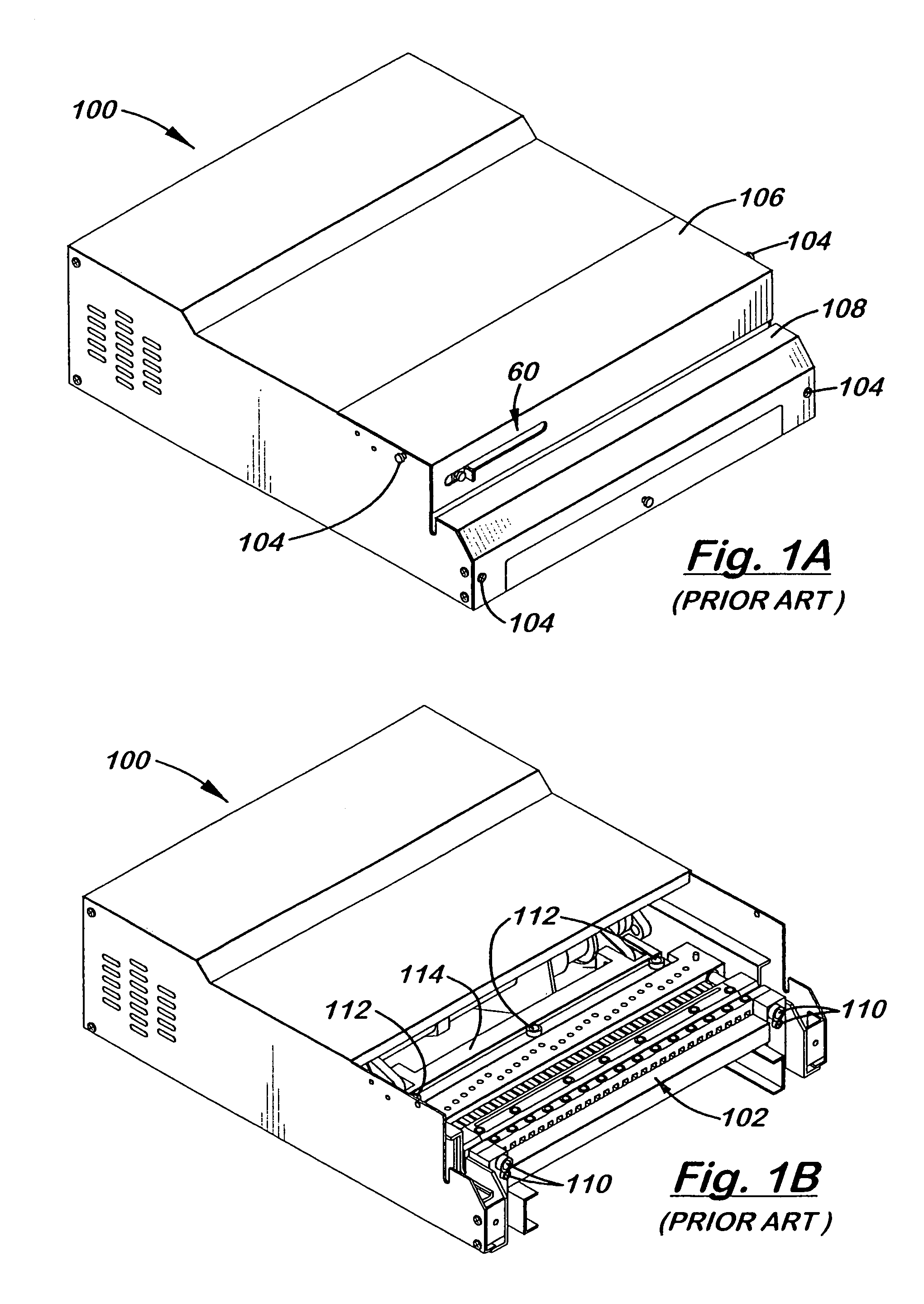
[0037]Referring to FIGS. 3–6, there is shown one, but not the only, embodiment of the invented punch machine 10. Punch machine 10 comprises machine housing 12, with hinged top lid 14, front drawer 16 and sidewalls 18, 18. The housing 12 encloses an interior space for holding the workings of the machine, including the die assembly 20, front cross bar 22, push-bar 24, and the drive system, including connecting rods 26, crankshaft 28, gear box, motor, and wiring. The drive system may be of various designs, such as that used in a conventional bolt-in die machine or others that are well known to those skilled in the field of punch equipment.
[0038]Starting the description toward the front of the machine 10, front cross bar 22 extends across the interior space to provide a front support surface for die assembly 20. Die assembly 20 is installed by sliding it through sidewall opening 30 and between cross bar 22 and push-bar 24. During this installation, the die 32 slides along cross bar 22 a...
PUM
Property
Measurement
Unit
length
aaaaa
aaaaa
thickness
aaaaa
aaaaa
distance
aaaaa
aaaaa
Abstract
Embodiments of an punch machine and a quick-change die assembly are shown and described. The die assembly may be quickly installed and removed from the punch machine, without bolting or unbolting of either machine housing or the die assembly itself. The die assembly is slid into the machine through a hole in the machine housing and into a position which mates part of the die assembly with the push-bar. A clamp, with a handle outside the machine, is then pivoted against the die assembly. The push-bar is adapted to be self-supporting without being bolted to the die assembly, keeping the push-bar in place without manual adjustment and alignment. The die assembly preferably includes a die, pin retainer, and punch pins, and preferably includes a flexible, pivotal, or hinged pin strap to secure the pins to the retainer. The preferred die assembly includes a positioning system that biases the pin retainer with its pin heads out from the die a proper distance for easy and unobstructed sliding into the machine housing and into a channel of the bar that drives the die assembly. The die assembly preferably includes a system for consistent referencing between various die assemblies, for reducing the instances in which the paper stop must be adjusted when a die assembly is changed.
Description
[0001]This application is a continuation of, and claims priority of prior, co-pending U.S. Utility patent application Ser. No. 10 / 003,758, filed Oct. 30, 2001, entitled “Hole Punch Quick-Change Die Assembly With Positioning System,” and issued on Jun. 15, 2004 as Pat. No. 6,748,839, which is a continuation of U.S. Utility patent application Ser. No. 09 / 547,816, filed Apr. 11, 2000, entitled “Hole Punch Quick-Change Die Assembly with Pin Strap and Positioning System,” issued on Apr. 2, 2002 as U.S. Pat. No. 6,363,826, which is a continuation in-in-part of U.S. Utility patent application Ser. No. 09 / 076,920 filed May 12, 1998, entitled “Hole Punch Quick-Change Die Assembly with Pin Strap and Positioning System” and issued on Apr. 11, 2000 as U.S. Pat. No. 6,047,623, which is a continuation-in-part of U.S. Utility patent application Ser. No. 08 / 611,301, entitled “Hole Punch with Quick-Change Die Assembly,” filed Mar. 5, 1996, issued on Jun. 30, 1998 as U.S. Pat. No. 5,771,768.BACKGROUN...
Claims
Application Information
Patent Timeline
Application Date:The date an application was filed.
Publication Date:The date a patent or application was officially published.
First Publication Date:The earliest publication date of a patent with the same application number.
Issue Date:Publication date of the patent grant document.
PCT Entry Date:The Entry date of PCT National Phase.
Estimated Expiry Date:The statutory expiry date of a patent right according to the Patent Law, and it is the longest term of protection that the patent right can achieve without the termination of the patent right due to other reasons(Term extension factor has been taken into account ).
Invalid Date:Actual expiry date is based on effective date or publication date of legal transaction data of invalid patent.