Hole punch quick-change die assembly with positioning system
- Summary
- Abstract
- Description
- Claims
- Application Information
AI Technical Summary
Benefits of technology
Problems solved by technology
Method used
Image
Examples
Embodiment Construction
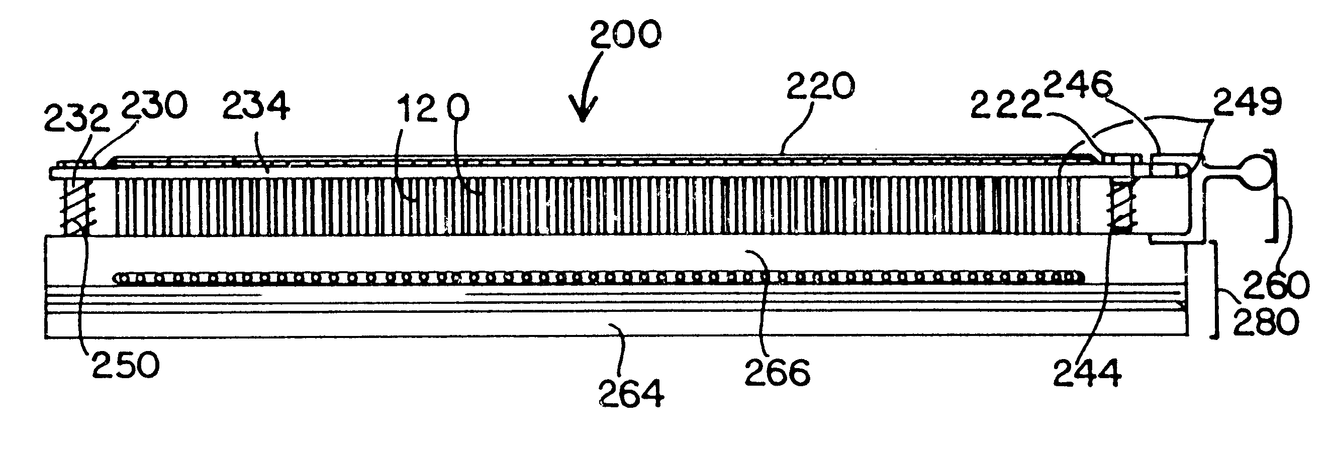
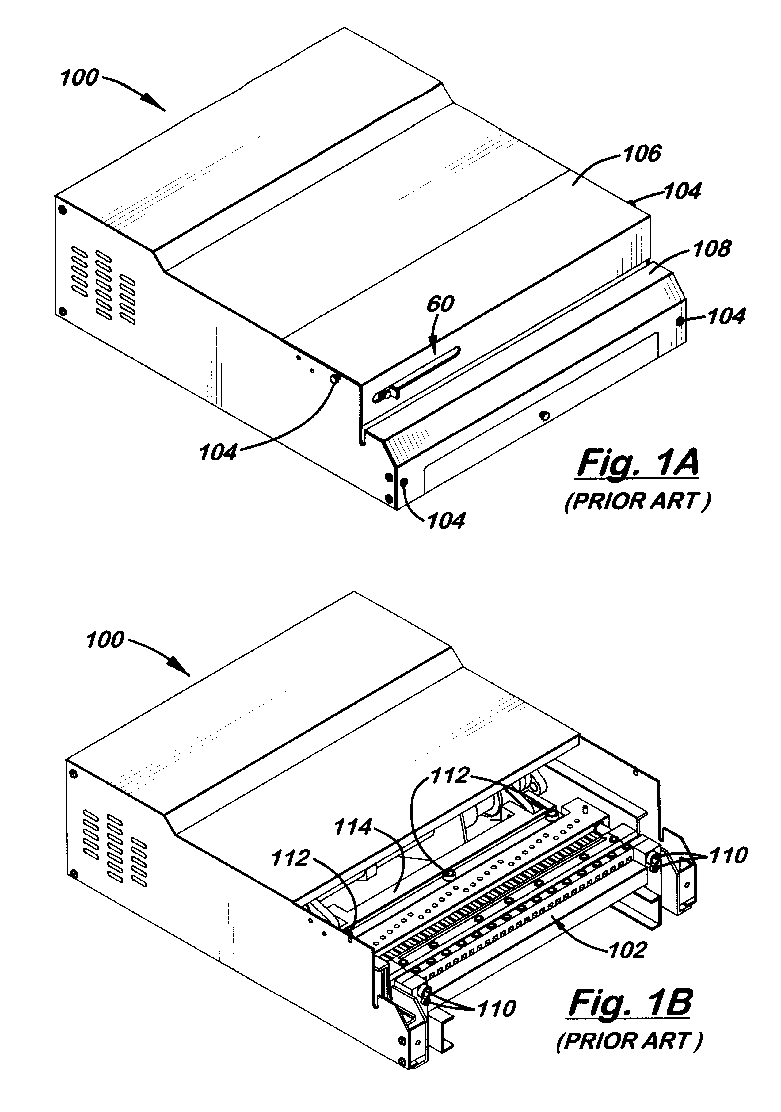
Referring to FIGS. 3-6, there is shown one, but not the only, embodiment of the invented punch machine 10. Punch machine 10 comprises machine housing 12, with hinged top lid 14, front drawer 16 and sidewalls 18, 18'. The housing 12 encloses an interior space for holding the workings of the machine, including the die assembly 20, front cross bar 22, push-bar 24, and the drive system, including connecting rods 26, crankshaft 28, gear box, motor, and wiring. The drive system may be of various designs, such as that used in a conventional bolt-in die machine or others that are well known to those skilled in the field of punch equipment.
Starting the description toward the front of the machine 10, front cross bar 22 extends across the interior space to provide a front support surface for die assembly 20. Die assembly 20 is installed by sliding it through sidewall opening 30 and between cross bar 22 and push-bar 24. During this installation, the die 32 slides along cross bar 22 and the pin ...
PUM
| Property | Measurement | Unit |
|---|---|---|
| Distance | aaaaa | aaaaa |
Abstract
Description
Claims
Application Information
 - R&D
- Intellectual Property
- Life Sciences
- Materials
- Tech Scout
- Unparalleled Data Quality
- Higher Quality Content
- 60% Fewer Hallucinations
Browse by: Latest US Patents, China's latest patents, Technical Efficacy Thesaurus, Application Domain, Technology Topic, Popular Technical Reports.
© 2025 PatSnap. All rights reserved.Legal|Privacy policy|Modern Slavery Act Transparency Statement|Sitemap|About US| Contact US: help@patsnap.com


