
Fuel delivery unit

a technology of fuel delivery and fuel tank, which is applied in the direction of liquid fuel feeders, machines/engines, and feed systems, etc., to achieve the effect of simple structure, simple manner, and reliable prevention of jamming

Inactive Publication Date: 2006-05-02
CONTINENTAL AUTOMOTIVE GMBH
View PDF9 Cites 0 Cited by
  • Summary
  • Abstract
  • Description
  • Claims
  • Application Information

AI Technical Summary

Benefits of technology

[0006]This design enables the delivery pump to be activated as a function of the filling of the surge chamber. This makes it possible to switch off the delivery pump if the fuel level in the surge chamber drops below a designated limit. It can therefore be ensured that the suction region of the delivery pump is situated at all times below the fuel level. Therefore, even if the surge chamber is virtually empty, air is reliably prevented from being sucked up by the delivery pump and blocking the lines leading to the internal combustion engine. In addition, damage to the delivery pump by it running dry is reliably prevented.
[0012]Sloshing movements of the fuel may exert short-term effects on the level sensor, thereby creating an erroneous signal that the fuel in the surge chamber has dropped below a minimum amount. According to another advantageous development of the invention, the influence of sloshing movements of the fuel can be kept particularly small if the pipe of the level sensor includes an opening that constricts the flow of air or fuel and therefore damps the movements of the fuel in the pipe.

Problems solved by technology

Furthermore, a reed switch of this type delivers an unambiguous switching signal which can be reliably assigned to a certain filling level of fuel.

Method used


Image

  • Fuel delivery unit
  • Fuel delivery unit

Examples


Embodiment Construction

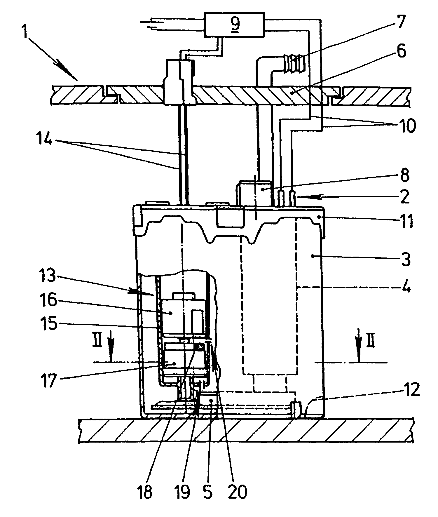
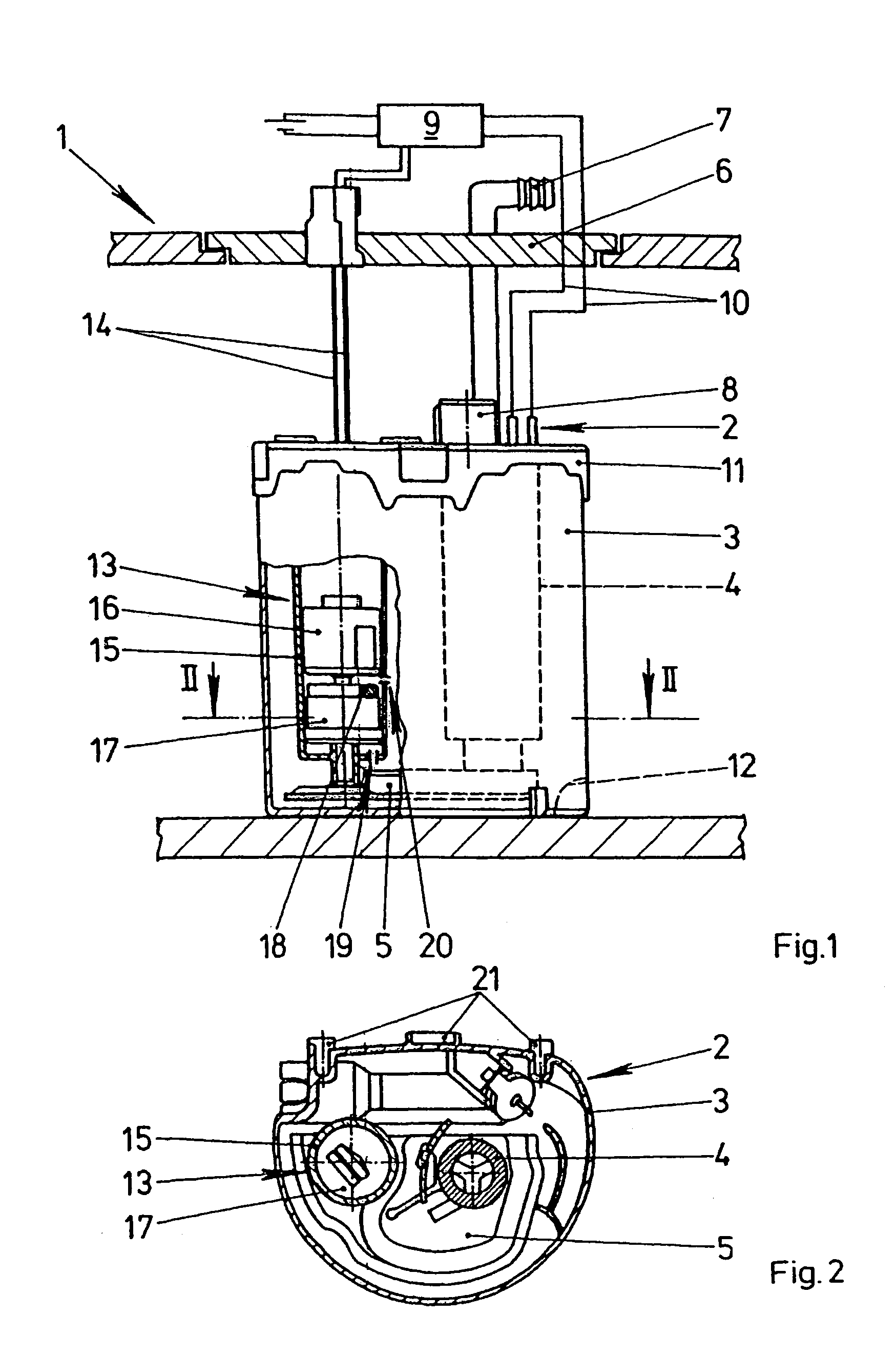
[0019]FIG. 1 shows a fuel tank 1 of a motor vehicle having a fuel delivery unit 2 which is arranged in it and is intended for delivering fuel. The fuel delivery unit 2 has a delivery pump 4 which is arranged in a surge chamber 3 and is driven by an electric motor. The delivery pump 4 delivers fuel via a filter 5, which is arranged in the surge chamber 3, to a connecting branch 7 arranged on an installation closure 6 which seals an access opening into fuel tank 1. A forward flow line (not illustrated) leading to an internal combustion engine of the motor vehicle can be connected to the connecting branch 7. The pressure delivered by the delivery pump 4 is limited by a pressure regulator 8. The delivery pump 4 is supplied with electric current by an electronic control system 9 via electric lines 10. The surge chamber 3 is latched to surge chamber 11. The cover 11 enables the surge chamber 3 to exchange air with the remaining regions of the fuel tank 1 and enables fuel to pass in from a...


PUM


Abstract

The invention relates to a fuel delivery unit (2) that is disposed in the fuel tank (1) of a motor vehicle, the delivery unit comprising a level sensor (13) that detects when the amount of fuel in a surge chamber (3) falls below a minimum amount. When the fuel in the surge chamber (3) falls below a defined minimum, the supply of power to a delivery pump (4) that is driven by an electromotor is interrupted, thereby preventing the delivery pump (4) from delivering air when the surge chamber (3) is empty.

Description

BACKGROUND OF THE INVENTION[0001]The invention relates to a fuel delivery unit which is provided for arrangement in a fuel tank of a motor vehicle, having a surge chamber for collecting fuel and having a delivery pump for delivering fuel from the surge chamber to an internal combustion engine of the motor vehicle.[0002]Fuel delivery systems of this type are frequently used in modern motor vehicles and are known from practice. The surge chamber is generally arranged at a location in the fuel tank in which it is preferably filled during a first filling of the tank. The surge chamber is therefore also filled.[0003]A disadvantage of the known fuel delivery units is, however, that, when the surge chamber is virtually empty, air can be sucked in by the delivery pump and can accumulate in the lines leading to the internal combustion engine. When reserve fuel is fed in thereafter, the air situated in the lines prevents fuel from being able to be delivered to the internal combustion engine. ...

Claims


Application Information

Patent Timeline
Patent Type & Authority Patents(United States)
IPC IPC(8): F02M37/04F02M37/10
CPCF02M37/106
Inventor NATHER, HELMUTSINZ, WOLFGANG
Owner CONTINENTAL AUTOMOTIVE GMBH
Learn More