
Hydraulic friction fluid heater and method of using same

a technology of hydraulic fluid and heater, which is applied in the direction of fluid friction for heating, insulation, borehole/well accessories, etc., can solve the problems of affecting hydrate and wax formation, hydrate formation is a problem, and the temperature of the circulating fluid is increased. , to achieve the effect of increasing the temperature of the circulating fluid

Inactive Publication Date: 2006-05-02
SAIPEM AMERICA
View PDF9 Cites 33 Cited by
  • Summary
  • Abstract
  • Description
  • Claims
  • Application Information

AI Technical Summary

Benefits of technology

The system effectively melts hydrates and waxes, preventing blockages by generating sufficient heat using hydraulic friction, even in deep-sea environments where traditional methods fail, and can be deployed using existing ROV systems.

Problems solved by technology

The pressure, however, dramatically increases with depth, is which affects hydrate and wax formation.
In general, the deeper the water the more critical a problem hydrates and waxes become for oil company operators.
Typically, hydrate and wax formation becomes an issue at approximately 500 meters (1500 feet), and below approximately 1000 meters (3000 feet) presents serious problems for oil companies.
However, hydrate formation is a problem for existing subsea pipelines having no hydrate traps as well as for subsea well heads and associated equipment mounted thereon.
In the past, attempts have been made at subsea hydrate and wax remediation with the use of electric heaters powered by an ROV system, however, typical ROV systems do not have sufficient electrical power to generate the heat necessary to effectively remediate such formations.

Method used


Image

  • Hydraulic friction fluid heater and method of using same
  • Hydraulic friction fluid heater and method of using same
  • Hydraulic friction fluid heater and method of using same

Examples


Embodiment Construction

[0024]The hydraulic friction fluid heater of the present invention is based on the fluid power equation 1:

Power=Pressure×Flowrate,   (1)

where a change in pressure or flowrate will produce a change in power, and a power change is manifested as heat transfer as reflected in equations 2 and 3:

Heat Transfer=Power Drop=Pressure Drop×Flowrate, or   (2)

Heat Transfer=Power Drop=Pressure×Flowrate Increase.   (3)

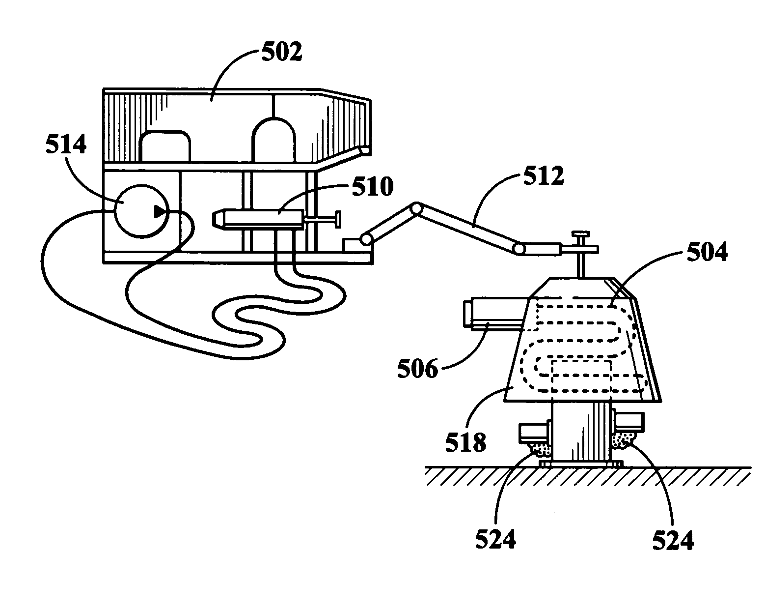
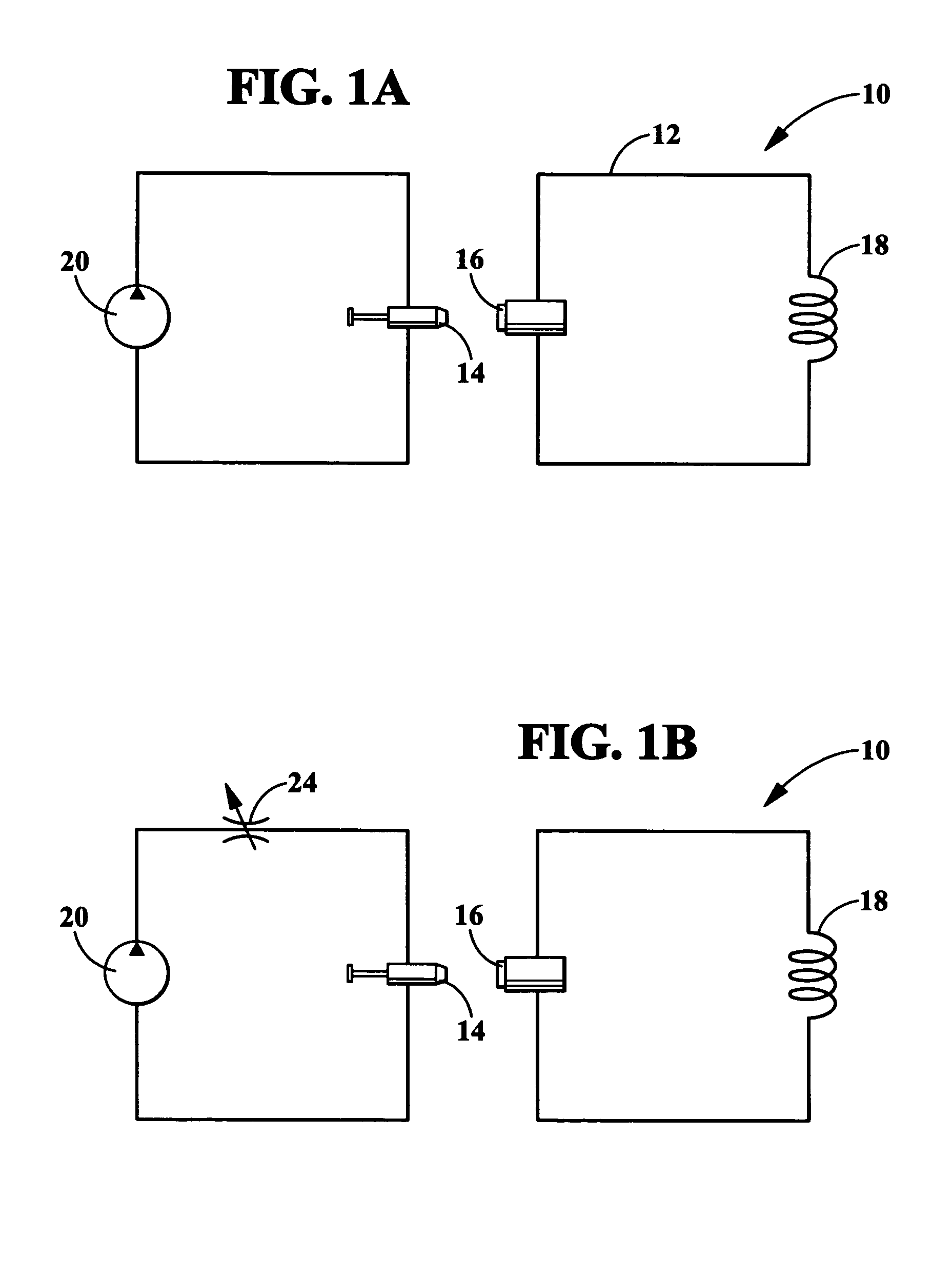
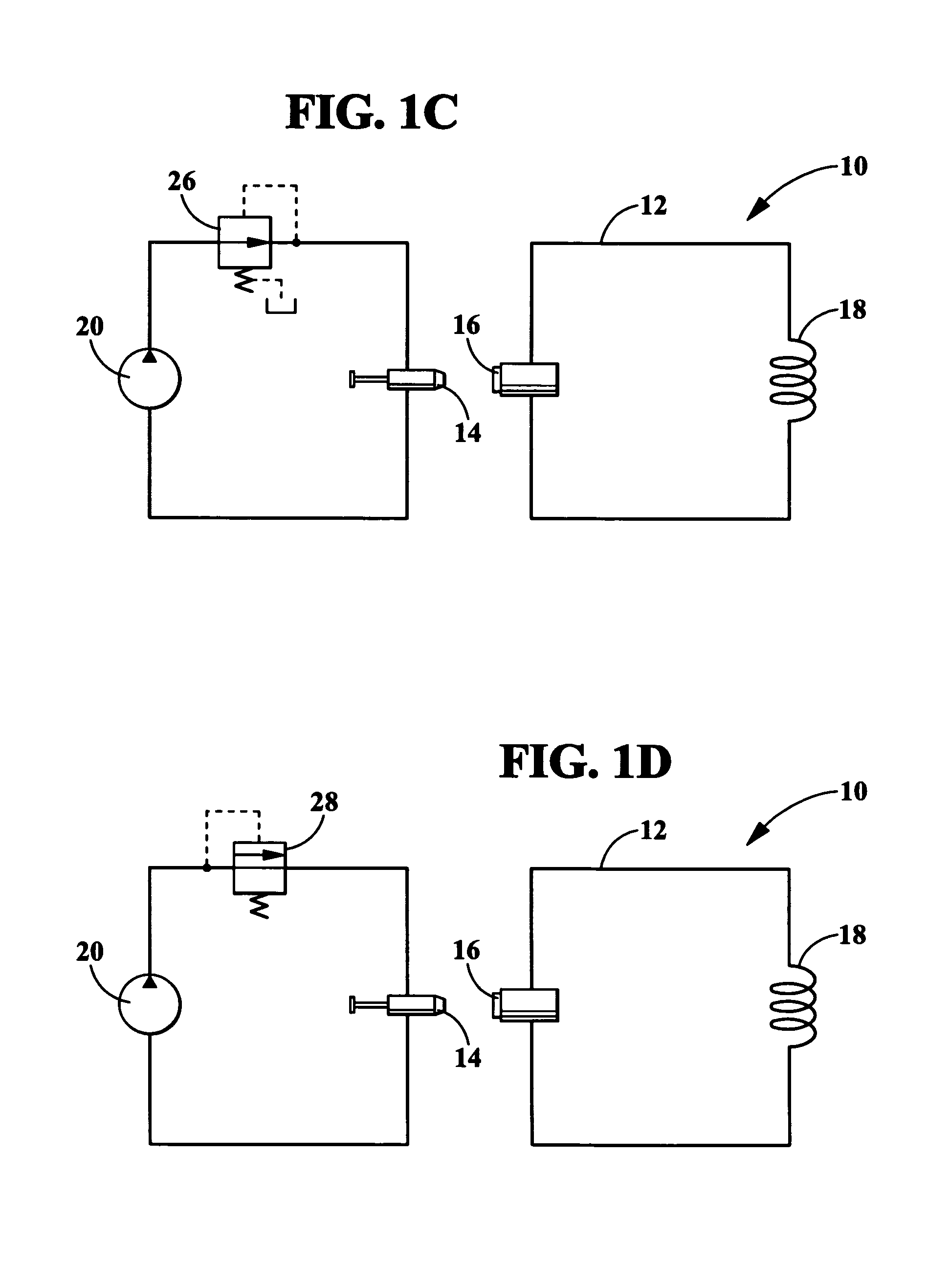
[0025]As described with respect to the illustrative embodiments described herein, a hydraulic friction fluid heater generates friction heat by circulating fluid through tubing and other pressure-reduction devices. There are three basic scenarios for utilizing the teachings of the present invention. The first scenario is a closed loop configuration in which heat is generated within a closed loop, the heat then being transferred to the desired structure to be heated. The second scenario includes a dual loop system with isolation between the fluids in each loop, where the heat generated ...


PUM


Abstract

A method and apparatus for heating a portion of a subsea structure is provided. The method includes pumping a fluid through a length of tubing such that the temperature of the fluid increases. The temperature increase of the fluid is created by friction in the tubing, and may be also be created by at least one pressure reducing device such as an orifice, pressure reducing valve, or relief valve. A subsea structure may be heated by transferring heat from fluid circulating in a closed loop configuration or by direct application of fluid to the subsea structure using a nozzle. A remotely operated vehicle may be utilized to transport some or all of the equipment necessary, including pumps, tubing, heat exchangers, nozzles and tanks. The remotely operated vehicle provides power to the pumps used for circulating fluid through the tubing.

Description

PRIORITY CLAIM[0001]This application claims priority to U.S. Provisional Patent Application Ser. No. 60 / 505,284, filed Sep. 23, 2003, which is incorporated herein by reference.BACKGROUND OF THE INVENTION[0002]The present invention relates generally to an apparatus and method for providing heat to a subsea pipeline or other structure, and more particularly relates to a hydraulic friction fluid heater for providing heat to a subsea pipeline or other structure.[0003]There often arises a need for heat to be supplied in a subsea environment. This frequently comes up in the offshore oil and gas industry. It is well known in the oil and gas industry that under certain pressure and temperature conditions the gases in a typical oil or gas well may form a solid hydrate or a solid wax within a pipeline. A hydrate is basically methane- or hydrocarbon-type ice. A wax is basically a paraffin-based solid formation. Hydrates and waxes are more likely to form under conditions of high pressures and l...

Claims


Application Information

Patent Timeline
Patent Type & Authority Patents(United States)
IPC IPC(8): F28D15/00E21B33/037E21B36/00
CPCE21B36/005E21B33/037F16L53/32F24V40/00F24V40/10
Inventor REID, BILLY JOE
Owner SAIPEM AMERICA
Learn More