Transmission lubricant cooling system

a technology of transmission lubricant and cooling system, which is applied in the direction of fluid gearings, machines/engines, and gearings, etc., can solve the problems of high cost of supplemental cooling circuits, and achieve the effects of reducing temperature, reducing flow rate, and reducing problems

Active Publication Date: 2006-05-02
HONDA MOTOR CO LTD
View PDF8 Cites 5 Cited by
  • Summary
  • Abstract
  • Description
  • Claims
  • Application Information

AI Technical Summary

Benefits of technology

[0013]The present invention is directed toward an improved transmission oil cooling circuit that eliminates or reduces the problems encountered in the art. The present invention is further directed toward a transmission oil cooling circuit wherein a portion of the cooled lubricating oil flow from the oil cooler is directed toward the secondary and counter shafts.
[0014]In accordance with the present invention, a vehicle transmission lubrication communication system includes a pump, a torque converter, an oil cooler, a shifting control assembly, a sump, and a plurality of shafts. The pump directs a first flow to the torque converter, and a second flow to the shifting control assembly. Oil from the torque converter flows through said oil cooler and, downstream the oil cooler, a first portion of cooled oil is directed to at least one of the plurality of shafts and a second portion of the cooled oil is directed to the sump.
[0015]In further accordance with the present invention, the transmission further includes secondary and counter shafts and the first portion of cooled oil is directed to the secondary and counter shafts. The flow of cooling oil to the secondary and counter shafts, as well as an increased flow rate through the torque converter and cooler, cooperate to maintain the lubricating oil at a relatively reduced temperature.

Problems solved by technology

Naturally, such supplemental cooling circuits are expensive, and introduce further concerns, such as space concerns, and are generally to be avoided.

Method used


Image

  • Transmission lubricant cooling system
  • Transmission lubricant cooling system
  • Transmission lubricant cooling system

Examples


Embodiment Construction

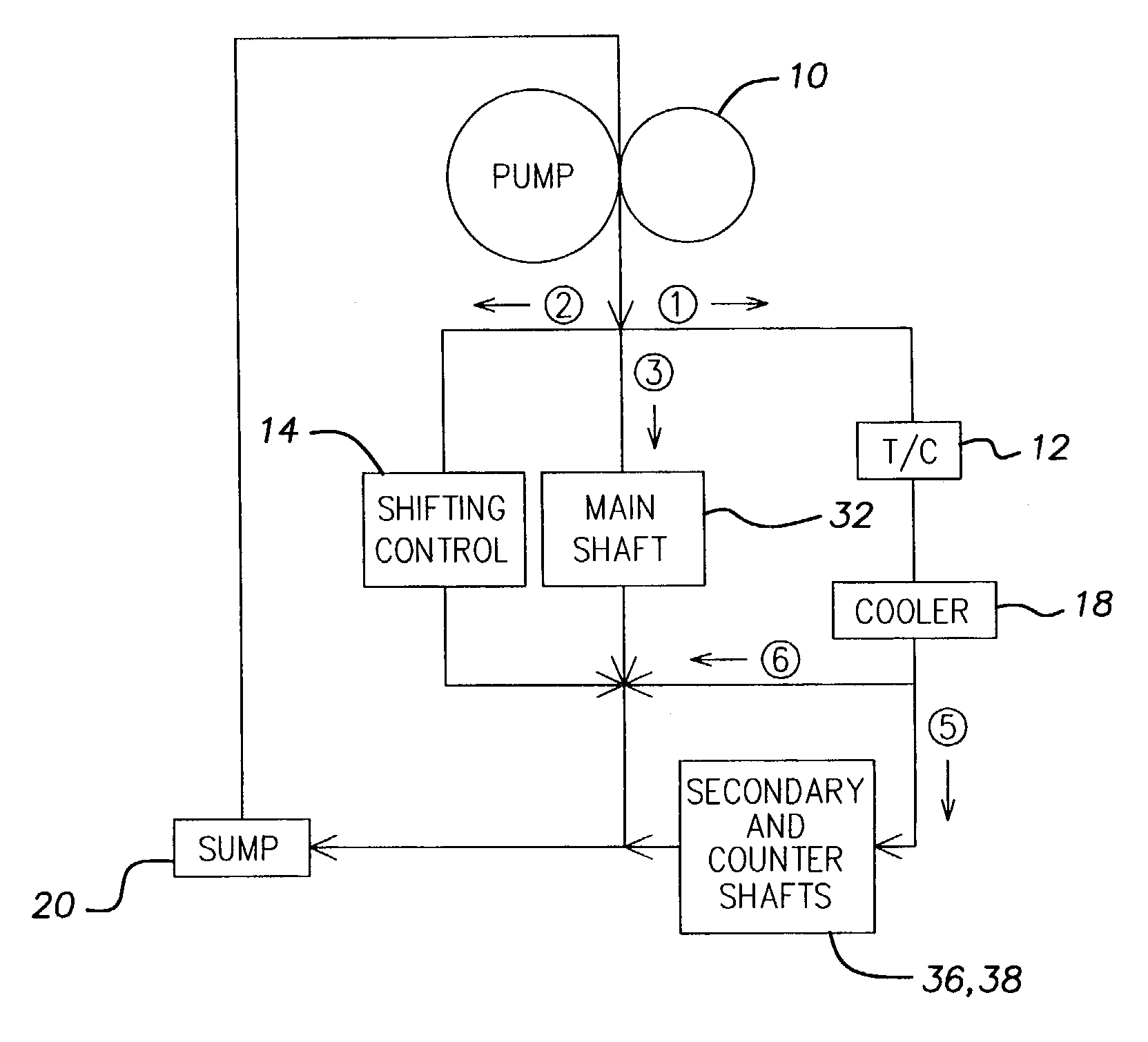
[0022]With reference to FIG. 4, a preferred embodiment of the present invention is schematically illustrated to include a pump 10, a torque converter 12, a main shaft 32, a secondary shaft 36, a counter shaft 38, a shifting control assembly 14, an oil cooler 18, and a sump 20.

[0023]The pump 10 supplies pressurized lubricating oil to three flows. The first flow {circle around (1)} is directed to the torque converter. The second flow {circle around (2)} is directed toward the shifting control assembly 14. The lubricating oil from the shifting control assembly is returned to the sump. The third flow {circle around (3)} is directed to the main shaft 32. The lubricating oil from the main shaft 32 is returned directly to the sump 20. The lubricating oil from the torque converter 12 is directed through the oil cooler 18. The cooled oil from the oil cooler 18 is split, with a first portion {circle around (5)} of the cooled oil being directed to the secondary and counter shafts 36, 38, and a...


PUM


Abstract

A vehicle transmission lubrication communication system including a pump, a torque converter, an oil cooler, a shifting control assembly, a sump, a main shaft, a counter shaft, and a secondary shaft. The pump withdraws lubricating oil from the sump and pumps the lubricating oil throughout the lubrication system. The pump directs a first flow to the torque converter, a second flow to the shifting control assembly, and a third flow to the main shaft. Oil from the torque converter flows through the oil cooler and, downstream the oil cooler, separates into a first portion of cooled oil that is directed to the secondary and counter shafts and a second portion of the cooled oil that is directed to the sump. Increased flow through the torque converter and oil cooler, as well as directing cooled oil to the secondary and counter shafts, reduces the oil temperature during normal and lockup modes of operation.

Description

BACKGROUND OF THE INVENTION[0001]1. Field of the Invention[0002]The present invention concerns transmission lubrication systems and, more particularly, transmission lubrication cooling systems.[0003]2. Description of Related Art[0004]Several vehicle transmission lubrication circuits are known in the art. A first known system is illustrated in FIG. 1, and generally includes a pump 10, a torque converter 12, a shifting control assembly 14, a shaft lubrication (lube) assembly 16, an oil cooler 18, and a sump 20. During normal operation of this system, about eighty percent of the lubricating fluid is directed through the shifting control assembly 14, while about twenty percent of the lubricating fluid is directed through the torque converter 12, shaft lube assembly 16, and oil cooler 18.[0005]The torque converter 12 may either be operated in a lock-up mode or in a non-lockup mode, with the non-lockup mode being referred to hereinafter as normal operation. During normal operation of such...

Claims


Application Information

Patent Timeline
Patent Type & Authority Patents(United States)
IPC IPC(8): F01M5/00F16H41/30F16H61/00
CPCF16H41/30F16H61/0021F16H57/0413F16H2061/0037
Inventor WHEELER, JEFF
Owner HONDA MOTOR CO LTD
Why Eureka
Try Eureka