Transport and storage container for liquids

Active Publication Date: 2006-05-02
PROTECHNA SA
View PDF6 Cites 31 Cited by
  • Summary
  • Abstract
  • Description
  • Claims
  • Application Information

AI Technical Summary

Benefits of technology

[0014]The flat upper peripheral rim of the upper profiled edge section of the latticework enclosure (jacket) of the transport and storage container ensures a save support action for a container stacked on top of a container positioned underneath by means of its corner and center legs. The wave profile formed in the double bar of the upper profiled edge section of the latticework enclosure (jacket), having preferably three peripheral welding projections, and the wave profile of the flattened (compressed to a flat shape) upper ends, having at least two welding projections, of the vertical rods of the latticework enclosure that are embodied as hollow profiled sections ensures an optimal projection welding connection of the vertical rods and the upper profiled edge section of the latticework enclosure with cruciform joints, wherein grooves that are formed in the outer wave profile of the double bar of the upper edge profile of the latticework enclosure, the double bar having an inner and an outer wave profile, enable an optimization of the pressing force of the welding electrodes. The support rim, which is springy to a limited extent and is oriented away from the double bar at a slant inwardly into the upper profiled edge section of the latticework enclosure and is supported with its inner rim on the upper end of the vertical rods, will contact, under the stacking load of a container stacked on top, across the entire width the upper ends of the vertical rods so that the welding conn

Problems solved by technology

When lateral sliding of a transport and storage container for liquids of the aforementioned kind, disclosed in European patent 0 370 307 B1, on a container of the same kind positioned underneath occurs during transport or stacking, there is the risk that the corner and center legs of the upper container slide inwardly off the upper profiled edge section, formed as a tube, of the latticework enclosure of the lower container.
This has the results that the upper area of the latticework enclosure of the lower container is widened under the weight of the upper container filled with liquid so that the screw connections of the top bars extending diagonally across the top of the inner plast

Method used


Image

  • Transport and storage container for liquids
  • Transport and storage container for liquids
  • Transport and storage container for liquids

Examples


Embodiment Construction

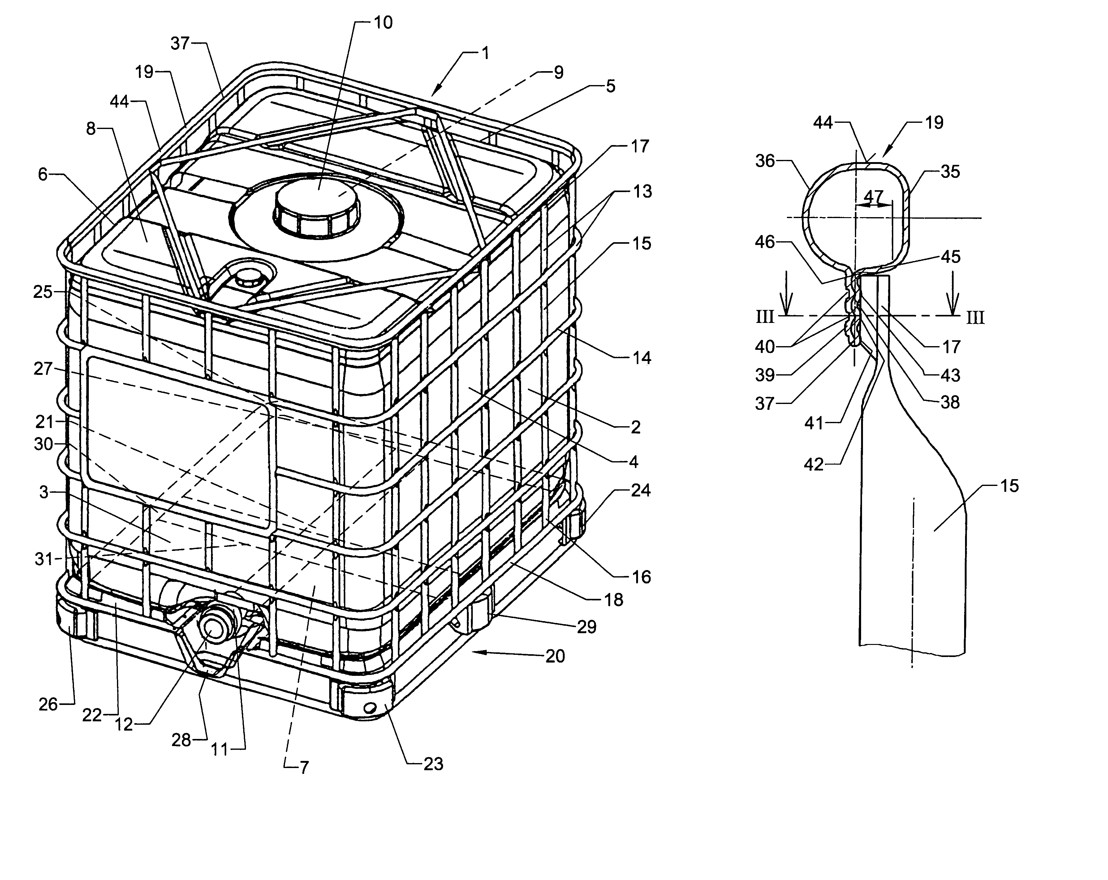
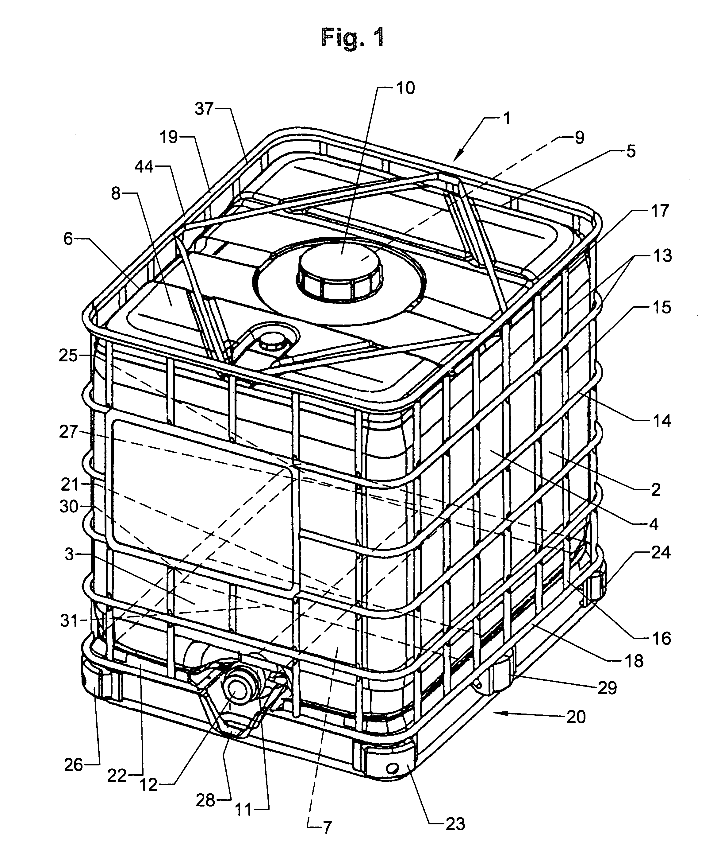
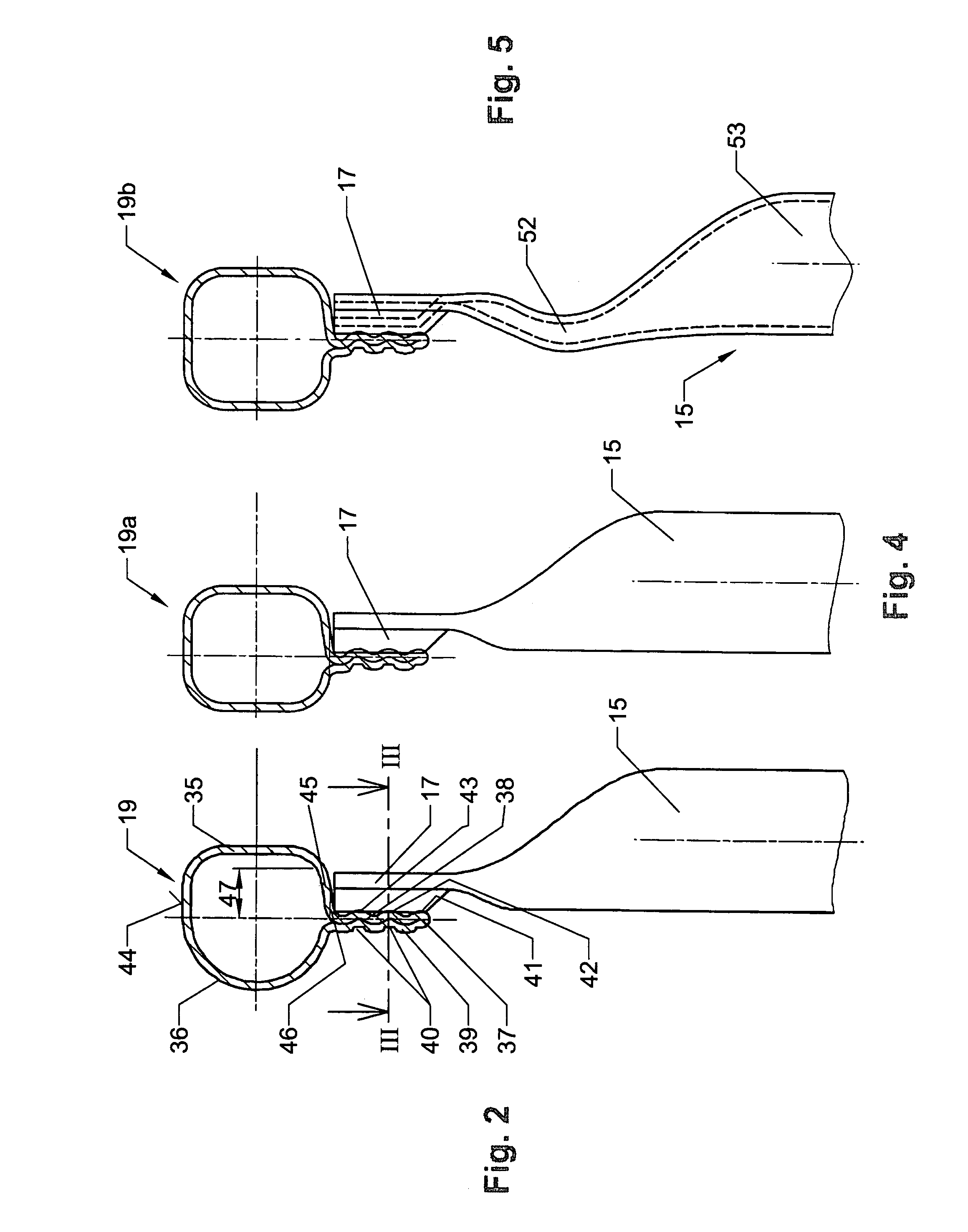
[0029]The transport and storage container 1 for liquids that is used as a disposable or reusable container has as its main components an exchangeable square inner container 2 made of plastic material that is comprised of four sidewalls 3–6, a bottom 7, and a top 8. A filling socket 9 is formed as part of the top 8 and is provided with a lid 10. A tapping socket 11 is formed as part of a lower section of the sidewall 3 and is provided with a tapping fixture 12. Moreover, an outer latticework enclosure 13 of crossed horizontal and vertical rods 14, 15 of metal is provided for receiving the inner container 2, wherein the ends 16, 17 of the vertical rods 15 are welded to lower and upper peripheral profiled edge sections 18, 19 of the latticework enclosure 13. A pallet-shaped bottom frame 20 is provided also and has length and width dimensions complying with European standards.

[0030]The bottom 7 of the inner container 2 forming a drainage bottom is provided with a centrally arranged drai...


PUM


Abstract

A transport and storage container for liquids has a pallet bottom frame, a latticework enclosure connected to the bottom frame, and an inner container received in the enclosure. The vertical rods of the latticework enclosure are connected to upper and lower peripheral profiled edge sections. The vertical rods are hollow and have flattened upper ends shaped to a wave profile with welding projections. The upper profiled edge section is a hollow profiled section formed to a double bar that extends peripherally and transversely to the vertical rods and is shaped to have inner and outer wave profiles engaging one another. The outer wave profile has grooves, and the inner wave profile forms welding projections. The upper ends of the vertical rods and the double bar are connected by projection welding. The upper profiled edge section has a flat upper rim for supporting legs of a container stacked on top.

Description

BACKGROUND OF THE INVENTION[0001]1. Field of the Invention[0002]The invention relates to a transport and storage container for liquids. The container comprises a pallet-like bottom frame for an exchangeable inner container of plastic material having four sidewalls, a bottom, and a top. A closable filling socket is formed as a part of the top. A tapping socket is formed as part of a lower portion of one of the sidewalls and is provided with a tap fixture. A latticework enclosure having horizontal and vertical rods of metal is provided for receiving the inner container, wherein the ends of the vertical rods are welded to lower and upper peripheral profiled edge sections.[0003]2. Description of the Related Art[0004]When lateral sliding of a transport and storage container for liquids of the aforementioned kind, disclosed in European patent 0 370 307 B1, on a container of the same kind positioned underneath occurs during transport or stacking, there is the risk that the corner and cente...

Claims


Application Information

Patent Timeline
IPC IPC(8): B65D19/00B65D19/10B65D77/04B65D77/06B65D88/10
CPCB65D77/0466
Inventor SCHUTZ, UDO
Owner PROTECHNA SA
Why Eureka
Try Eureka