Cone crusher

a cone crusher and cone crusher technology, applied in the field of cone crusher cone crusher cone liner and mantle liner, can solve the problems of affecting the quality of crushing materials, and increasing the speed of moving crushed materials, so as to achieve the effect of adequate inlet siz

Inactive Publication Date: 2006-05-02
EARTHTECHNICA
View PDF9 Cites 16 Cited by
  • Summary
  • Abstract
  • Description
  • Claims
  • Application Information

AI Technical Summary

Benefits of technology

[0038]In accordance with the above structural arrangement, the crushing surface of the concave liner is approximately 90° to the horizontal plane in the first area, and therefore the crush material may be securely transferred to the next stage (the second area). In the second area, moreover, the crushing surface of the concave liner is 57° to 62° to the horizontal plane, thereby enabling an adequate size of the inlet in the second area to be maintained

Problems solved by technology

However, this causes the speed of moving the crush material to be increased, so that the fine-crushing performance is deteriorated.
However, this causes the crush material to be clogged up, thereby enabling the electric power consumption and the mechanical vibration to be increased.
Nevertheless, even if such a crushing camber having an optimal shape is formed, taking the above-mentioned conditions into account, paired upper and lower liners are selectively worn away in an increased period of operation (partial abrasion) to provide an extremely partial uneven shape for these liners, so that the sh

Method used


Image

  • Cone crusher
  • Cone crusher
  • Cone crusher

Examples


Embodiment Construction

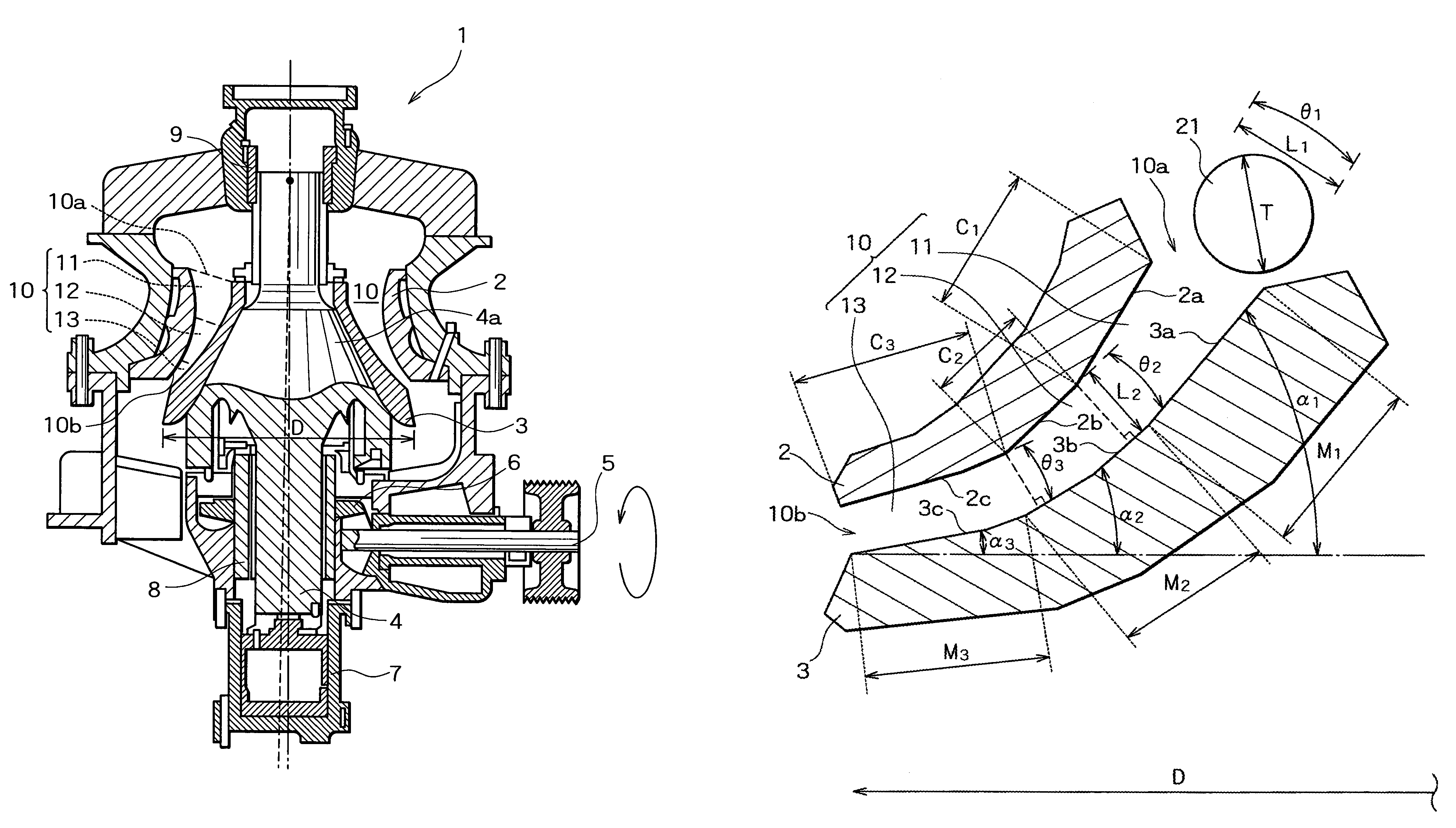
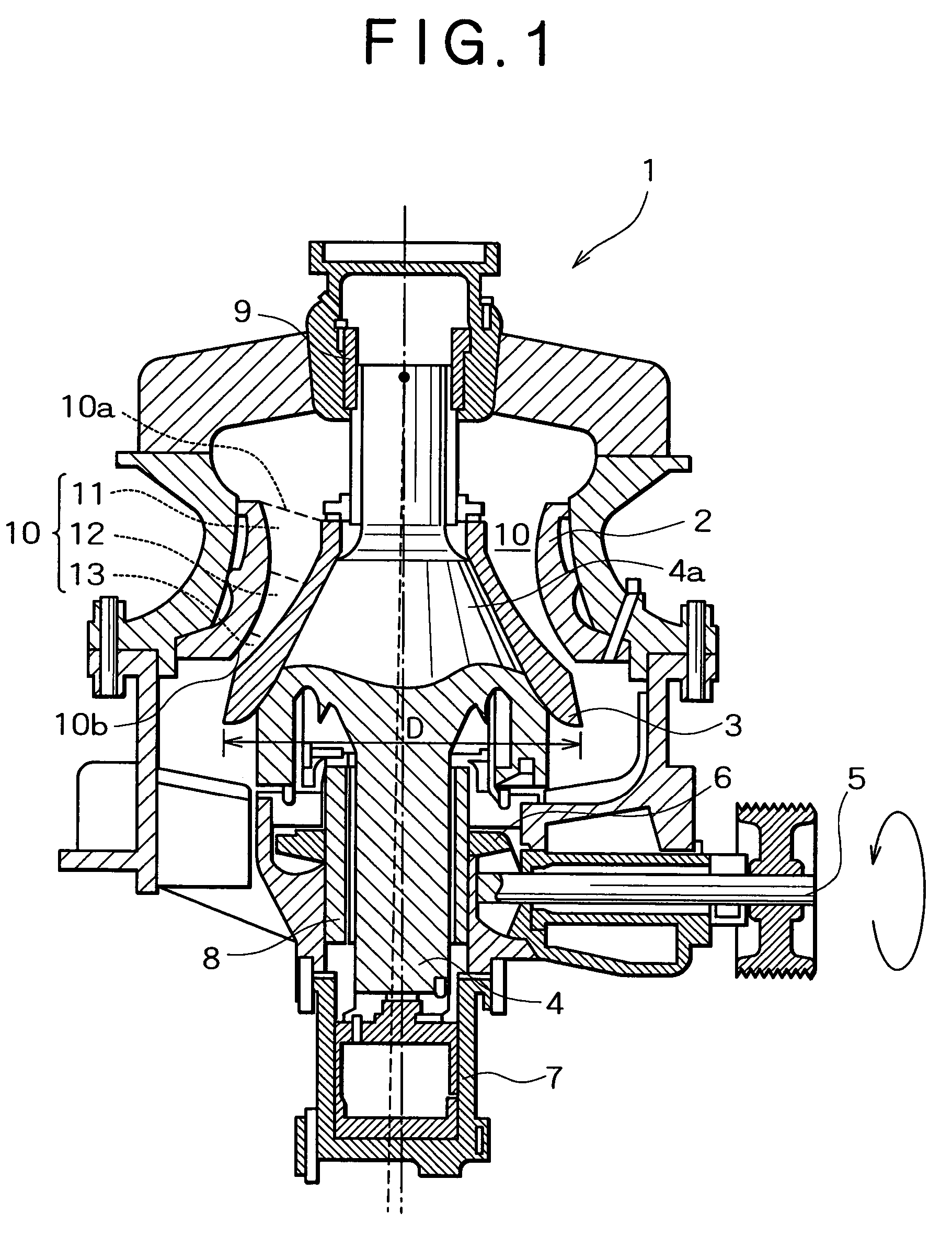
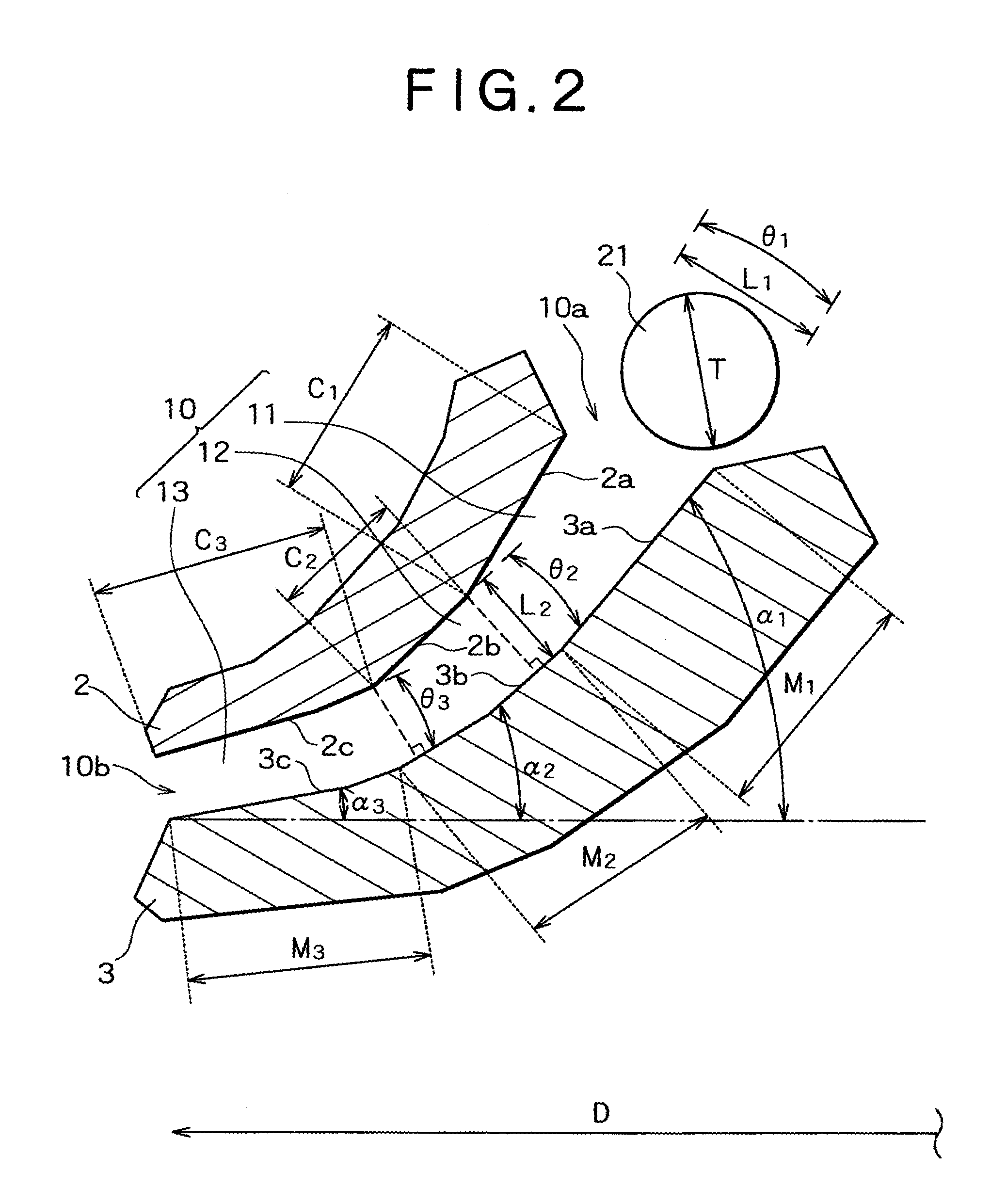
[0048]In the following, preferred embodiments of the present invention will be described, referring to FIGS. 1 to 9. FIG. 1 is a sectional view of a cone crusher in an embodiment according to the invention.

[0049]In FIG. 1, the cone crusher 1 is equipped with a concave liner 2 and a mantle liner 3, wherein a crushing chamber 10, whose width gradually increases from an inlet 10a to an outlet 10b, is formed between the liners 2 and 3. The crushing chamber 10 comprises a first region or area 11, a second region or area 12 and a third region or area 13 which are sequentially arranged from the inlet 10a to the outlet 10b.

[0050]The above-described concave liner 2 has an approximately cone shape, and the outer periphery surface thereof is fixed to the main body of the cone crusher 1. At the same time, the inner periphery surface thereof forms the crushing chamber 10. The position of the concave liner 2 is fixed and the height thereof is adjustable.

[0051]The above-described mantle liner 3 h...


PUM


Abstract

A crushing chamber is formed between a concave liner and a mantle liner. The concave liner has a first area surface having a length of T to √2T; a second and a third area surface; which surfaces are gradually inclined from the side of the inlet for the crushing chamber. The mantle liner has a first tapered surface having a length of greater than T, a cross angle of less than 20° and an inclination angle of greater than 60°; a second tapered surface having a length of greater than 0.5T and a cross angle of 5° to 10°; and a third tapered surface having an inclination angle of 45° to 50°. The area surfaces as well as the tapered surfaces are continuously arranged in a curvilinear manner. The shapes enhance the throughput of goods in a good fine-crushing performance, reducing the uneven abrasion due to the action.

Description

BACKGROUND OF THE INVENTION[0001]1. Field of the Invention[0002]The present invention relates to a concave liner and a mantle liner in a cone crusher, which is used to produce coarse aggregate and fine aggregate for concrete, asphalt-ply material or the like.[0003]2. Description of the Related Art[0004]A conventional cone crusher is equipped with a stationary concave liner and a mantle liner fixed to a mounting base as a movable member which is capable of approaching the inner periphery of the concave liner and separates therefrom, and a crushing chamber is formed between the concave liner and the mantle liner, so that a material to be crushed, i.e., a crush material, is crushed in the crushing chamber, thereby enabling predetermined products to be obtained. Therefore, such liners for the cone crusher was basically designed on the basis of combining the shapes of the concave liner with that of the mantle liner, which liners form a crusher chamber providing the most favorable crushin...

Claims


Application Information

Patent Timeline
IPC IPC(8): B02C2/06B02C2/04B02C2/00
CPCB02C2/005
Inventor HAMADA, TAKESHIHAMAGUCHI, MASAKIINOMATA, SHOJITAKANAMI, HIROTOSHIYUKI, HIROYUKI
Owner EARTHTECHNICA
Why Eureka
Try Eureka