
Modular tooling apparatus with tapered locater system

a module and locater technology, applied in the field of modular fixturing apparatus, can solve the problems of increasing the weight of the fixturing apparatus, increasing the set-up time and hence the cost of the process, and limiting the support of so as to reduce the number of components and restrain the part undergoing inspection

Inactive Publication Date: 2006-05-02
WAL III H JAMES VANDER
View PDF4 Cites 35 Cited by
  • Summary
  • Abstract
  • Description
  • Claims
  • Application Information

AI Technical Summary

Benefits of technology

[0005]The present invention overcomes the difficulties of the prior art by providing a modular fixturing system which is capable of supporting objects, even large objects, having a wide variety of shapes or configurations and, more particularly, is capable of locating the center of datum holes while providing a leveling function, which minimizes the number of components. This is achieved by providing a sliding pin or locator means with one or more tapered surfaces and a Z-adjustment member. In addition, the present invention provides a locking feature that rotationally locks the sliding pin, which can restrain the part undergoing inspection from rotation.
[0012]It can be appreciated that the fixturing component of the present invention provides a hole locator that also provides support along the Z-axis to the part undergoing inspection. In addition, the Z-axis support may be adjusted to accommodate a variety of parts. Furthermore, the component may be modified so that the locator means can limit rotation of the part undergoing inspection.

Problems solved by technology

However, these universal hole locators have provided limited support to the part undergoing inspection.
When setting up a fixturing apparatus, an increase in the number of components to hold and set up the part increases the set-up time and hence the cost of the process.
Moreover, the weight of the fixturing apparatus increases.

Method used


Image

  • Modular tooling apparatus with tapered locater system
  • Modular tooling apparatus with tapered locater system
  • Modular tooling apparatus with tapered locater system

Examples


Embodiment Construction

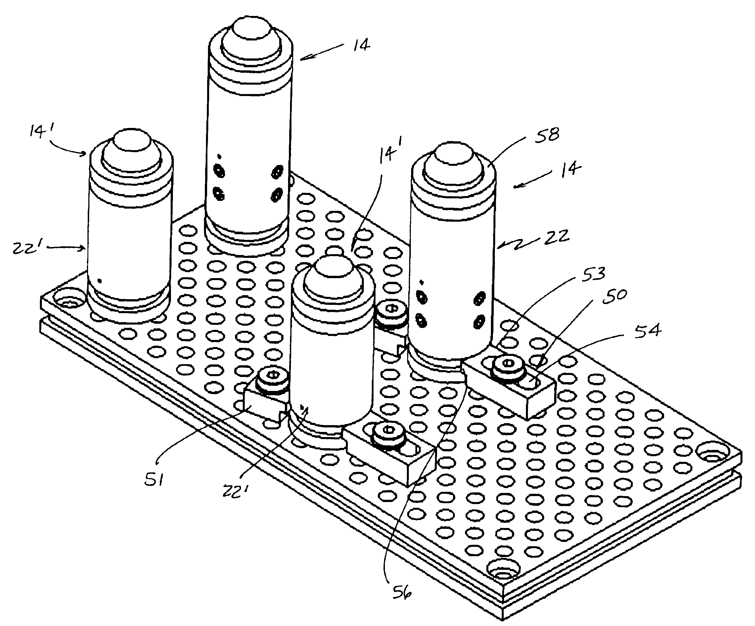
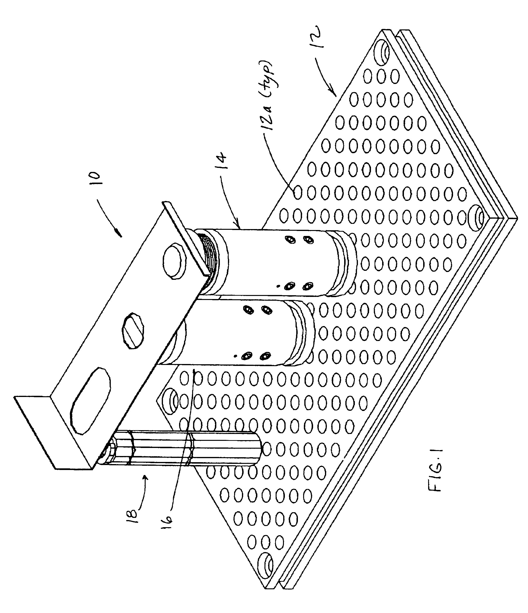
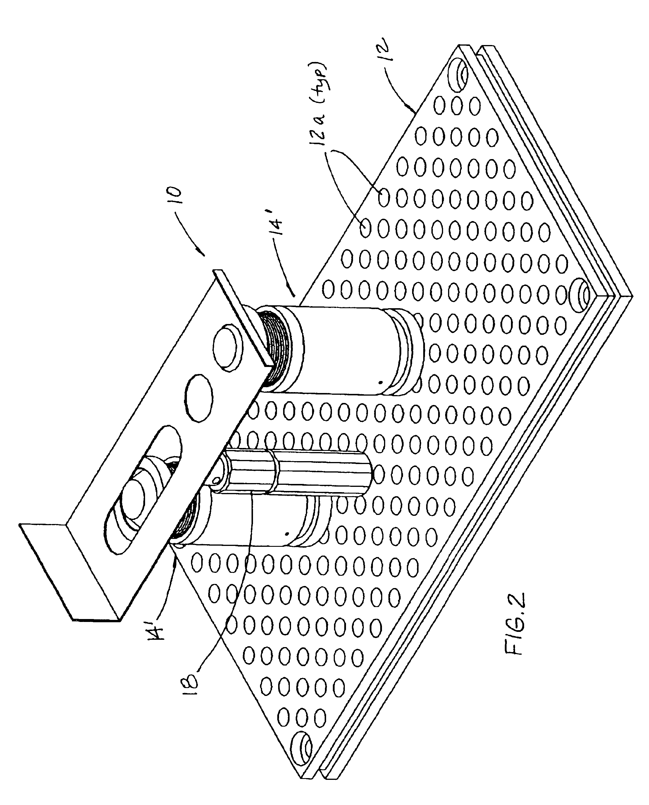
[0030]Referring to FIGS. 1-4, the numeral 10 generally designates a modular fixturing apparatus of the present invention. Modular fixturing apparatus 10 includes a base plate or platform 12 and plurality of fixturing components 14, 16, 18, and 20 (FIGS. 18 and 19) that are mounted to platform 12 for leveling and supporting an object, such as a part. Platform 12 includes a plurality of mounting openings 12a which are spaced at intervals along two axes, namely the X and Y axes, to provide a coordinate or locator system for measuring or locating the part undergoing inspection or the like. In the illustrated embodiment, components 14 and 16 comprise datum hole or slot locators and, further, provide a support surface on which the part being inspected maybe leveled and onto which the part may be clamped to provide both upward and downward (+ or −Z) restraint to the part. In addition, as will be more fully described below, components 14 and 16 may be used to limit rotation of the part unde...


PUM


Abstract

A modular fixturing apparatus component includes a body and a locator mechanism. The locator means is supported in the body for linear movement along the longitudinal axis of the body and for rotational movement about the longitudinal axis. The locator mechanism is provided to locate a center of an opening in an article undergoing inspection or the like. The modular fixturing apparatus component further includes a support surface that is provided at the body and that provides support for the article along the longitudinal axis. In this manner, when the component is mounted to a modular fixturing base plate, the fixturing apparatus component of the present invention provides a datum hole locator mechanism with a sliding action along the Z-axis and, further, provides Z-axis support for the article undergoing inspection or the like. Optionally, the locator mechanism may be rotationally locked to provide an additional, rotational restraint to the article undergoing inspection.

Description

TECHNICAL FIELD AND BACKGROUND OF THE INVENTION[0001]The present invention relates to a fixturing apparatus and, more particularly, to a modular fixturing apparatus used to support an object undergoing manufacturing, inspection, or testing processes or the like. The invention is particularly suitable for supporting or holding a part or component undergoing quality control inspection by a coordinate measuring machine (CMM) and may also be used to support or hold objects undergoing light to moderate manufacturing processing, such as assembling, soldering, laser-jet and water-jet cutting, welding, light-machining, or the like.[0002]A typical modular fixturing apparatus includes a platform or base plate and a series of fixturing components that can be mounted to the base plate to provide support and leveling for the part undergoing inspection. The base plate includes a plurality of mounting openings that permit the fixturing components to be secured to the base plate in a variety of dif...

Claims


Application Information

Patent Timeline
IPC IPC(8): B23Q3/00B23Q3/18B23Q16/00B23Q37/00
CPCB23Q3/183B23Q1/035B23Q37/00B23Q16/001
Inventor WAL, III, H. JAMES VANDER
Owner WAL III H JAMES VANDER
Learn More