Co-extruded taper shaft

a co-extruded, tubular shaft technology, applied in the direction of catheters, other domestic objects, transportation and packaging, etc., can solve the problems of difficult difficult use of standard catheters with relatively constant diameters, and complicated material selection for each of the various catheter components

Inactive Publication Date: 2006-05-02
ABBOTT CARDIOVASCULAR
View PDF30 Cites 59 Cited by
  • Summary
  • Abstract
  • Description
  • Claims
  • Application Information

AI Technical Summary

Problems solved by technology

A standard catheter having a relatively constant diameter is difficult to use in some of the smaller arteries and in cases of more advanced stenosis where the artery is closed to such an extent that the catheter cannot be extended through the lesion.
Due to the different responsibilities of each tubular member, inner 10 and outer 12 tubular members generally have different desired material characteristics, which complicates the selection of materials for each of the various catheter components.
Thus, when dealing with a single tubular member the material selection is particularly difficult.
The joint between the proximal and distal shafts, however, often makes for an undesirable, abrupt transition between shaft sections.
The abrupt transition caused by joining a larger diameter proximal shaft to a smaller diameter distal shaft not only creates a weak point on the catheter shaft at the point of joinder, but the joint region itself is typically stiff and can interfere with the overall flexibility of the catheter shaft.
However, there are several limitations and problems associated with the necking down process.
Such weak spots are more susceptible to leaks, kinks and cracks, which adversely affect the reliability of the catheter.
Further, the

Method used


Image

  • Co-extruded taper shaft
  • Co-extruded taper shaft
  • Co-extruded taper shaft

Examples


second embodiment

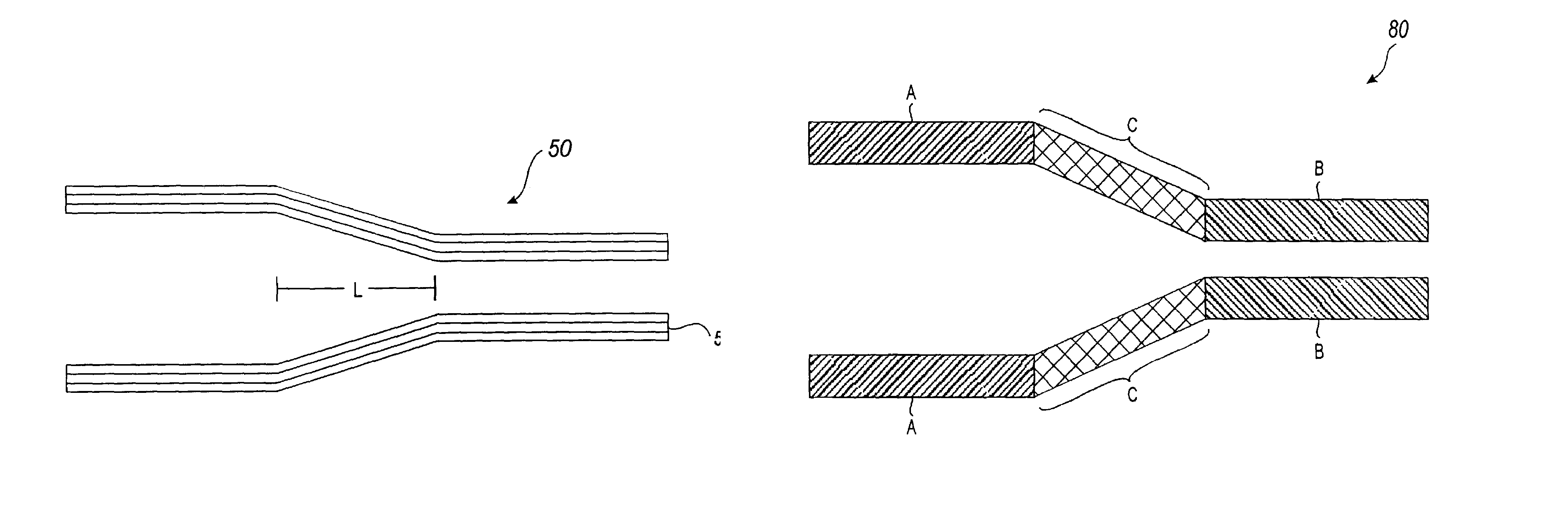
[0045]The embodiment of the present invention discussed above describes the formation of a multi-layer tapered shaft 50 through the use of a co-extrusion tapering process. The resulting multi-layer tapered shaft may then be further modified through post-process necking. The added necking process makes the tapered shaft more pressure resistant and stiffer. Further, it is possible to achieve a higher tolerance with necking. The tighter necking control is possible since the necking of the shaft is being done on a metal core and through a tight tolerance die. Thus, the invention may consist of tapering a co-extruded multi-layer shaft with a co-extruder system and a taper puller to approximately ¾ of the desired dimension and then necking down to the final desired dimension. This combination of co-extrusion tapering and neck tapering provides finer control over both the dimensions and the stiffness of the tapered shaft. For example, if neck tapering is performed for the entire taper, the...

third embodiment

[0048]the present invention involves tapering a shaft consisting of a variable transition between a first material and a second material. FIG. 10 provides a side cross-sectional view of tapered shaft 80 having a variable transition between materials A and B. Note that the transition between materials may be relatively quick and immediate or may have a longer transitional segment C (as illustrated) that consists of a combination or composite of materials A and B.

[0049]A shaft 80 having a variable transition may be formed by an extrusion tapering process using the same taper puller described above. Rather than the first and second materials being tapered and extruded together to form a shaft having multi-layers, this embodiment involves concurrently tapering and extruding a shaft formed by extruding a first material and then a second material to form a single variable layer tubular shaft 80. Note, that a variable transition layer may also be used as one of several layers in a multi-la...


PUM

PropertyMeasurementUnit
Lengthaaaaaaaaaa
Thicknessaaaaaaaaaa
Pressureaaaaaaaaaa

Abstract

An apparatus and method for providing a co-extruded, tapered multi-layer shaft. A co-extruded, tapered multi-layer shaft may be fabricated by selecting a first material for the inner layer of the shaft and a second material for the outer layer of the shaft. The first and second materials are then co-extruded by a co-extrusion system including a puller with programmable tapering capabilities. The system forms a hollow tubing having an inner layer and an outer layer, wherein the tubing has the desired tapered characteristics. The result is a tapered tubular shaft having an inner layer and an outer layer.

Description

[0001]This application is a continuation application of U.S. patent application Ser. No. 09 / 464,932, filed Dec. 16, 1999 now U.S. Pat. No. 6,579,484.BACKGROUND OF THE INVENTION[0002]1. Field of the Invention[0003]This invention relates generally to tubular shafts. More particularly, the present invention involves tapering a co-extruded tubular shaft (e.g., for use in catheters).[0004]2. Description of Related Art[0005]In percutaneous transluminal coronary angioplasty (PTCA), catheters are inserted into the cardiovascular system via the femoral artery under local anesthesia. A pre-shaped guiding catheter is positioned in the coronary artery, and a dilatation catheter having a distensible balloon portion is advanced through the guiding catheter into the branches of the coronary artery until the balloon portion traverses or crosses a stenotic lesion. The balloon portion is then inflated with a fluid to compress the atherosclerosis in a direction generally perpendicular to the wall of t...

Claims


Application Information

Patent Timeline
IPC IPC(8): A61M25/00B29C48/09
CPCA61M25/0009B29C47/0023B29C47/065B29C47/26A61M25/0045B29C47/0026B29C47/0033Y10T428/1352B29C47/34B29C2947/92438B29C2947/926B29C2947/92647B29L2031/7542Y10T428/1393B29C48/09B29C48/10B29C48/13B29C48/21B29C48/335B29C48/355B29C2948/92438B29C2948/926B29C2948/92647
Inventor TIERNAN, STEPHEN J.LEE, JEONG S.CHOW, MINA W. B.SCHAIBLE, STEPHEN G.
Owner ABBOTT CARDIOVASCULAR
Why Eureka
Try Eureka